J1000 3
Commom specifications
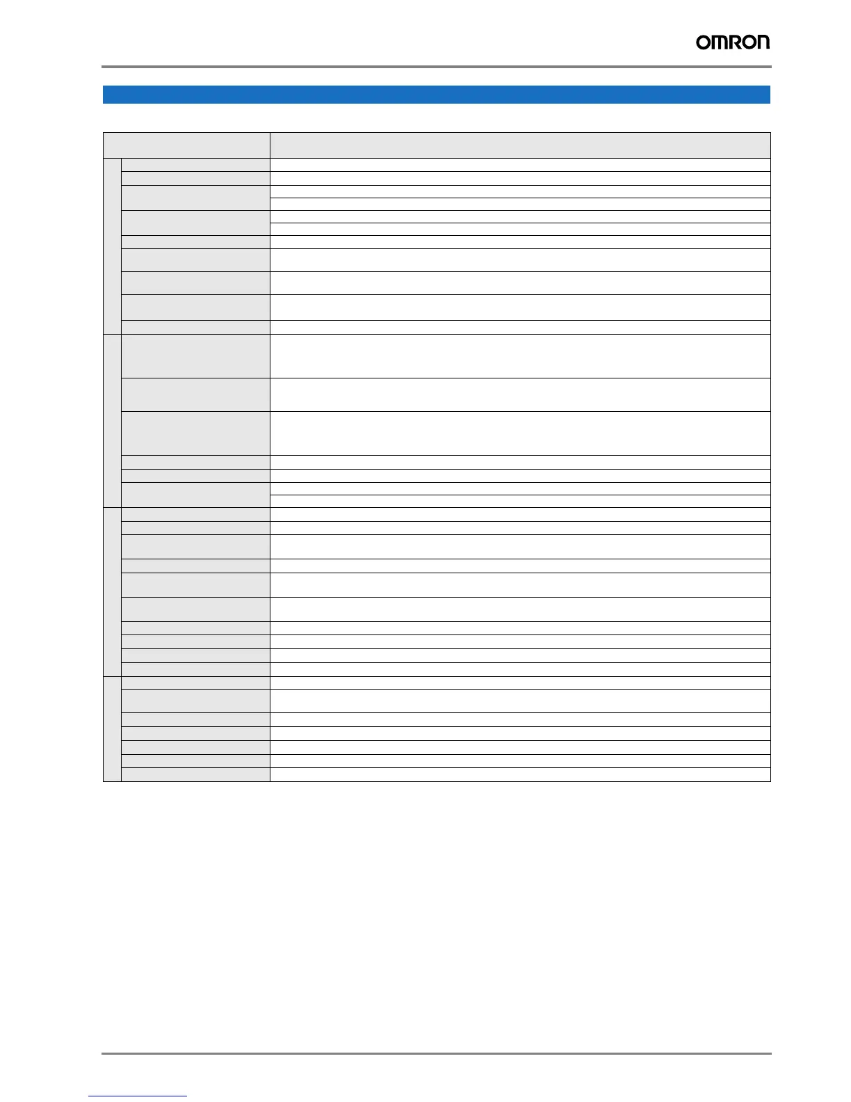
Specifications
Model number
JZA@
Specifications
Control functions
Control methods
V/f control
Output frequency range
0.1..400 Hz
Frequency tolerance
Digital set value: ±0.01% (-10..+50 ºC)
Analogue set value: ±0.1% (25 ±10 ºC)
Resolution of frequency set value
Digital set value: 0.01 Hz (<100 Hz), 0.1 Hz (>100 Hz)
Analogue set value: 1/1000 of maximum frequency
Resolution of output frequency
0.01 Hz
Overload capability
Heavy duty use: 150% rated output current for one minute
Normal duty use: 120% rated output current for one minute
Frequency set value
0..10 V (20 kΩ), 4..20 mA (250 Ω), 0..20 mA (250 Ω)
Frequency setting value (selectable)
Braking torque
(short term peak torque)
Short-term average deceleration torque: 150% (up 1.5 kW), 100% (for 1.5 kW), 50% (for 2.2 kW), 20% (fof bigger size)
Continous regenerative torque: Aprox 20% (125% with optional braking resistor, 10%ED, 10 s, braking transistor built itn)
V/f Characteristics
Possible to program any V/f pattern
Functionality
Inputs signals
Five of the following input signals are selectable: Forward/reverse run (3-wire sequence), fault reset, external fault (NO/NC
contact input), multi-step speed operation, Jog command, accel/decel time select, external baseblock, speed search com-
mand, UP/DOWN command, accel/decel hold command, LOCAL/REMOTE selection, emergency stop fault, emergency
stop alarm, self test
Output signals
Following output signals are selectable (NO/NC contact output, MA, MB and MC realay: Fault, running, zero speed, speed
agree, frequency detection (output frequency <= or => set value), undervoltage detection, minor error, during baseblock, op-
eration mode, inverter run ready, during fault retry, reverse running, during speed search.
Standard functions
Full-range automatic torque boost, slip compensation, 9-step speed operation (max.), restart after momentary power loss,
DC injection braking current at stop/start (50% of inverter rated current, 0.5 sec, or less), frequency reference bias/gain, ME-
MOBUS communications (Option), fault retry, speed search, frequency upper/lower limit setting, overtorque detection, fre-
quency jump, accel/decel time switch, accel/decel prohibited, S-curve accel/decel
Analogue inputs
1 analogue input, 0..10 V, 4..20 mA, 0..20 mA
Braking/acceleration times
0.01..6000 s
Display
Optionally frequency, current or set value
Error and status LED
Protection functions
Motor overload protection Electronic thermal overload relay
Instantaneous overcurrent Motor coasts to a stop at approx. 250% of inverter rated current
Overload
Heavy Duty: Motor coasts to a stop after 1 minute at 150% of inverter rated output current
Normal Duty: Motor coasts to a stop after 1 minute at 120% of inverter rated output current
Overvoltage Motor coasts to a stop if DC bus voltage exceed 410 V (double for 400 V class)
Undervoltage
Stops when DC bus voltage is approx. 190 V or less (double for 400 V class)
(approx. 150 V or less for single-phase series)
Momentary power loss
Following items are selectable: not provided (stop if power loss is 15 ms or longer), continuous operation if power loss is
approx. 0.5 s or shorter, continuous operation
Cooling fin overheat Protected by thermistor
Stall prevention level Stall prevention during acceleration/deceleration and constant speed operation
Ground fault Protected by electronic circuit (operation level is approx. 250% of rated output current)
Power charge indication Indicates until the main circuit voltage reaches 50 V.
Ambient conditions
Degree of protection
IP20, NEMA1
Cooling
Cooling fan is provided for 200 V (3-phase) 0.75 kW (1HP) to 4.0 KW, 200V (single-phase) 1.5 KW
400 V 1.5 kW (2HP) to 4.0 KW, others are self-cooling
Ambient humidity
95% RH or less (without condensation)
Storage temperature
-20 ºC..+60 ºC (short-term temperature during transportation)
Installation
Indoor (no corrosive gas, dust, etc.)
Installation height
Max. 1000 m
Vibration
Up to 9.8 m/s
2
at 10 to less than 20 Hz, Up to 6.37 m/s
2
at 20 to 50 Hz

 Loading...


