J1000 7
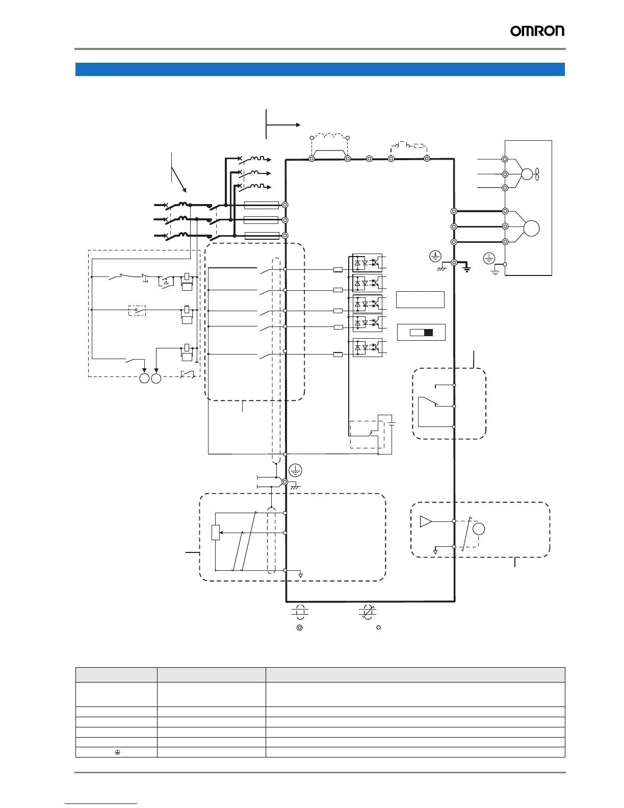
Standard connections
Main circuit
Installation
Terminal Name Function (signal level)
R/L1, S/L2, T/L3
Main circuit power supply input Used to connect line power to the drive.
Drives with single-phase 200 V input power use only terminals R/L1 and S/L2
(T/L3 is not connected to anything)
U/T1, V/T2, W/T3
Inverter output Used to connect the motor
B1, B2
Braking resistor connection Available for connecting a braking resistor or the braking resistor unit option.
+2, +1
DC reactor connection Remove the short bar between +2 and +1 when connecting DC reactor (option)
+1, –
DC power supply input For power supply input (+1: positive electrode; – : negative electrode)*
Grounding For grounding (grounding should conform to the local grounding code.)
SA
Motor
Cooling fan
Forward run/stop
Reverse run/stop
External fault
Fault reset
0 to +10 VDC
(2 mA)
Fault
J1000
Main circuit
Control circuit
Fault relay
1 MCCB
MC
2 MCCB
r1
s1
t1
R/L1
S/L2
T/L3
S1
S2
S3
S4
S5
<3>
<1>
<2>
-
B1+1+2 B2
R/L1
S/L2
T/L3
MC
THRX
TRX
MC
TRX
MC MA
U/T1
V/T2
W/T3
24
V
MA
MB
MC
IV
M
M
r1
s1
t1
FU
FV
FW
U
V
W
SC
AM
AC
+
-
AM
+V
A1
AC
2 kΩ
Ground
10 Ω or less (400 V class)
100 Ω or less (200 V class)
Setting power supply
+10.5 max. 20 mA
Digital output
250 VAC, 10 mA to 1 A
30 VDC, 10 mA to 1 A
(default setting)
2 MCCB
THRX
OFF
ON
MC
SA
SA
Jumper
DIP switch S1
Sink
Source
main circuit terminal
shielded line
twisted-pair shielded line
control terminal
<4>
<5>
<6>
<7>
0 to +10 V (20 kΩ)
(0)4 to 20 mA (250Ω)
Terminals +1, +2, −, B1, and B2
are for connecting options.
Never connect power supply
lines to these terminals.
For single phase 200 V
power supply, use
R/L1 and S/L2.
Three phase
power supply
200 to 240 V
Option unit
connector
Thermal relay for
motor cooling fan
Multi-step
speed 1
main/aux switch
Digital inputs
(default setting)
Main speed
frequency
reference.
Multi-function
programmable
Shield ground
terminal
DIP
switch S3
+24 V 8 mA
DC reactor
(option)
Thermal relay
(option)
Braking resistor
(option)
Analog monitor
output
Monitor
output

 Loading...


