EasyManua.ls Logo

Omron J1000 User Manual

Omron J1000
232 pages
To Next Page IconTo Next Page
Page #1 background imageLoading...
Page #1 background image
Note: Specifications subject to change without notice.
Manual No. SIEP-C--OY
Austria
Tel: +43 (0) 2236 377 800
www.industrial.omron.at
Belgium
Tel: +32 (0) 2 466 24 80
www.industrial.omron.be
Czech Republic
Tel: +420 234 602 602
www.industrial.omron.cz
Denmark
Tel: +45 43 44 00 11
www.industrial.omron.dk
Finland
Tel: +358 (0) 207 464 200
www.industrial.omron.fi
France
Tel: +33 (0) 1 56 63 70 00
www.industrial.omron.fr
Germany
Tel: +49 (0) 2173 680 00
www.industrial.omron.de
Hungary
Tel: +36 (0) 1 399 30 50
www.industrial.omron.hu
Italy
Tel: +39 02 32 681
www.industrial.omron.it
Middle East & Africa
Tel: +31 (0) 23 568 11 00
www.industrial.omron.eu
Netherlands
Tel: +31 (0) 23 568 11 00
www.industrial.omron.nl
Norway
Tel: +47 (0) 22 65 75 00
www.industrial.omron.no
Poland
Tel: +48 (0) 22 645 78 60
www.industrial.omron.com.pl
Portugal
Tel: +351 21 942 94 00
www.industrial.omron.pt
Russia
Tel: +7 495 648 94 50
www.industrial.omron.ru
Spain
Tel: +34 913 777 900
www.industrial.omron.es
Sweden
Tel: +46 (0) 8 632 35 00
www.industrial.omron.se
Switzerland
Tel: +41 41 748 13 13
www.industrial.omron.ch
Turkey
Tel: +90 (0) 216 474 00 40
www.industrial.omron.com.tr
United Kingdom
Tel: +44 (0) 870 752 08 61
www.industrial.omron.co.uk
OMRON EUROPE B.V.
Wegalaan 67-69, NL-2132 JD, Hoofddorp, The Netherlands.
Tel: +31 (0) 23 568 13 00 Fax: +31 (0) 23 568 13 88 www.industrial.omron.eu
J1000 USER’S MANUAL
Manual No. SIEP-C71060633-01-OY
J1000
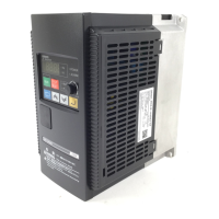
Compact General Purpose Inverter
Model: JZA
200 V Class Three-Phase Input 0.1 to 0.4 kW
200 V Class Single-Phase Input 0.1 to 1.5 kW
400 V Class Three-Phase Input 0.2 to 4.0 kW
USER’S MANUAL
Manual No.
SIEP-C71060633-01-OY
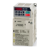
Table of Contents

Other manuals for Omron J1000

Questions and Answers:

Omron J1000 Specifications

General IconGeneral
BrandOmron
ModelJ1000
CategoryInverter
LanguageEnglish

Summary

Preface and General Safety

Preface

Provides an overview of the manual and applicable documentation, symbols, and terms.

General Safety Information

Details safety precautions, messages, warnings, and conventions for using the drive.

Receiving

Section Safety

Covers safety precautions related to handling and receiving the drive.

Model Number and Nameplate Check

Instructions for inspecting the drive for damage and verifying the model number on the nameplate.

Component Names

Illustrates and identifies the various components of the drive.

Mechanical Installation

Section Safety

Highlights safety precautions for mechanical installation.

Mechanical Installation Procedures

Details specifications, procedures, and environmental requirements for proper drive mounting.

Electrical Installation

Section Safety

Safety precautions for electrical wiring and connections.

Standard Connection Diagram

Provides a standard wiring diagram for connecting the drive and peripheral devices.

Main Circuit Connection Diagram

Illustrates the main power circuit connections for different drive models.

Terminal Block Configuration

Shows the main circuit terminal block configurations for various drive sizes.

Protective Covers

Procedure for removing and reattaching protective covers before wiring.

Main Circuit Wiring

Details specifications and procedures for safely wiring the main circuit.

Control Circuit Wiring

Instructions for wiring control circuit terminals, including digital inputs and outputs.

I/O Connections

Details on sinking/sourcing mode switch and transistor input signal configurations.

Main Frequency Reference

Configuration for analog input signal selection for main frequency reference.

Braking Resistor

Installation instructions and precautions for connecting a braking resistor.

Interlocking with Connected Machinery

Setup for interlock with application using the drive ready signal.

Wiring Checklist

A checklist to ensure all wiring connections are correct before test run.

Start-Up Programming & Operation

Section Safety

Safety precautions for initial drive operation and programming.

Using the Digital LED Operator

Guides on using the LED operator for commands, display, and parameter editing.

Drive and Programming Modes

Explains the two main operating modes: Drive Mode and Programming Mode.

Start-up Flowchart

Provides a step-by-step flowchart for basic drive start-up procedures.

Powering Up the Drive

Checklist and status display information for powering up the drive.

No-Load Operation Test Run

Procedure for operating the drive with the motor uncoupled from the load.

Test Run with Load Connected

Steps for running the motor and load together after a no-load test.

Verifying and Backing Up Parameter Settings

How to check parameter changes and save settings using Verify function or Copy function.

Test Run Checklist

Checklist items for performing a test run of the drive.

Parameter Details

Initialization Parameters

Parameters for configuring basic drive environment, access levels, and passwords.

Application Parameters

Parameters for frequency reference, Run command, DC Injection Braking, and other settings.

Tuning Parameters

Parameters for acceleration, deceleration, S-curves, slip, torque compensation, and carrier frequency.

Reference Settings

Parameters for entering various frequency reference values and limits.

Motor Parameters

Parameters for setting V/f characteristics and motor data for optimal control.

Terminal Functions

Parameters for assigning functions to multi-function digital input and output terminals.

Protection Functions

Parameters for motor overload, power loss, stall prevention, and other protection features.

Special Adjustments

Parameters for advanced adjustments like hunting prevention and overexcitation braking.

Operator Related Settings

Parameters concerning digital operator display settings and key functions.

Monitor Parameters

Parameters for viewing drive status, fault history, and maintenance information.

Troubleshooting

Section Safety

Safety precautions for troubleshooting procedures.

Motor Performance Fine Tuning

Information for counteracting oscillation, hunting, or faults during trial runs.

Drive Alarms, Faults, and Errors

Descriptions of drive faults, alarms, errors, and their possible solutions.

Fault Detection

Detailed fault displays, causes, and possible solutions.

Alarm Detection

Lists alarm codes, their causes, and possible solutions for non-fault conditions.

Operator Programming Errors

Identifies and explains operator programming error codes (oPE) and their solutions.

Diagnosing and Resetting Faults

Procedure to remove fault triggers and restart the drive.

Troubleshooting without Fault Display

Guides for resolving issues that do not cause alarms or faults.

Periodic Inspection & Maintenance

Section Safety

Safety precautions for performing periodic inspection and maintenance.

Inspection Procedures

Outlines recommended daily and periodic inspection items and corrective actions.

Periodic Maintenance

Details on drive maintenance monitors and replacement parts.

Drive Cooling Fans

Instructions for replacing drive cooling fans to ensure maximum product life.

Peripheral Devices & Options

Section Safety

Safety precautions for installing peripheral devices and options.

Drive Options and Peripheral Devices

Lists available peripheral devices and options for OYMC drives.

Connecting Peripheral Devices

Illustrates how the drive and motor connect with various peripheral devices.

Installing Peripheral Devices

Provides steps and precautions for installing various peripheral devices.

Communication Options

Details on available options for connecting drives to communication networks.

Appendix A: Specifications

Heavy Duty and Normal Duty Ratings

Defines Heavy Duty (HD) and Normal Duty (ND) load characteristics for drive capacity.

Single/Three-Phase 200 V Class Drive

Lists power ratings for single and three-phase 200 V class drives.

Three-Phase 400 V Class Drives

Lists power ratings for three-phase 400 V class drives.

Drive Specifications

Provides detailed electrical and environmental specifications for the drive.

Drive Watt Loss Data

Presents watt loss data for single-phase and three-phase models.

Drive Derating Data

Information on derating drive capacity based on temperature, altitude, and carrier frequency.

Appendix B: Parameter List

Parameter Groups

Lists all parameters categorized into groups for easy reference.

Parameter Table

A comprehensive table listing all drive parameters, their descriptions, and settings.

Defaults by Drive Capacity and ND/HD

Provides default parameter settings based on drive capacity and duty mode.

Appendix C: MEMOBUS/Modbus Communications

Section Safety

Safety precautions for MEMOBUS/Modbus communication setup.

MEMOBUS/Modbus Configuration

Explains how to configure the drive for MEMOBUS/Modbus communication.

Communication Specifications

Details communication interface, speeds, parameters, and protocols.

Connecting to a Network

Instructions for connecting the drive to a MEMOBUS/Modbus network.

MEMOBUS/Modbus Setup Parameters

Configuration parameters for MEMOBUS/Modbus serial communication.

Drive Operations by MEMOBUS/Modbus

Describes drive operations controllable via MEMOBUS/Modbus communications.

Communications Timing

Explains message timing for master-to-drive and drive-to-master communication.

Message Format

Details the structure of MEMOBUS/Modbus messages including content, slave address, function codes, data, and error check.

Message Examples

Provides examples of command and response messages for reading and loopback tests.

MEMOBUS/Modbus Data Table

Lists all MEMOBUS/Modbus data types: command, monitor, and broadcast data.

Changing Drive Parameters

How drive parameters are handled during changes via MEMOBUS/Modbus communication.

Communication Errors

Lists MEMOBUS/Modbus error codes, causes, and solutions.

Self-Diagnostics

Procedure to perform self-diagnosis of the serial communication interface circuits.

Appendix D: Standards Compliance

Section Safety

Safety guidelines for maintaining CE and UL standards.

European Standards

Details CE mark compliance with European safety and environmental regulations.

UL Standards

Information on UL/cUL mark, product testing, and compliance requirements.

User Setting Table

A table listing user-configurable parameters and their settings.

Related product manuals