0: READ Prohibited
The data in the operator are write protected. The READ operation cannot be performed.
1: READ Permitted
The data in the operator are not write protected. The READ operation can be performed.
u
o4: Maintenance Monitor Settings
n
o4-01: Accumulated Operation Time Setting
Parameter
o4-01 sets the cumulative operation time and allows the user to set the starting value of the accumulated operation
time displayed in monitor U4-01.
Note: The value in o4-01 is set in 10 h units. For example, a setting of 30 will set the cumulative operation time counter to 300 h. 300 h will also
be displayed in monitor U4-01.
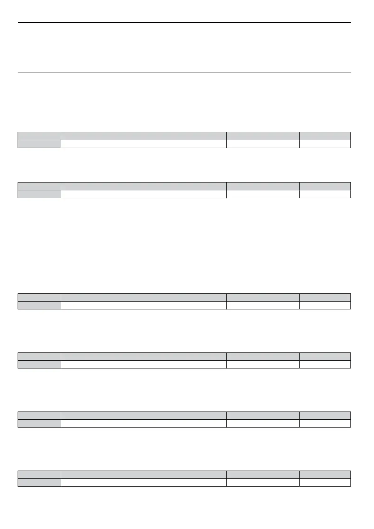
No. Name Setting Range Default
o4-01 Accumulated Operation Time Setting 0 to 9999 0
n
o4-02: Accumulated Operation Time Selection
Selects
the conditions for what is to be considered “accumulated operation time.” Accumulated operation time is displayed
in U4-01.
No. Name Setting Range Default
o4-02 Accumulated Operation Time Selection 0 or 1 0
Setting 0: Power On Time
The drive logs the time it is connected to a power supply, no matter if the motor is running or not.
Setting 1: Run Time
The
drive logs the time that the output is active, i.e., whenever a Run command is active (even if the motor is not rotating)
or a voltage is output.
n
o4-03: Cooling Fan Maintenance Setting
Sets the value of the cooling fan operation time base value used for the maintenance value displayed in U4-04. Be sure to
reset this parameter back to 0 if the cooling fan is replaced.
Note: 1. The value in o4-03 is set in 10 h units.
2. The actual maintenance time depends on the environment the drive is used in.
No. Name Setting Range Default
o4-03 Cooling Fan Operation Time 0 to 9999 0
n
o4-05: Capacitor Maintenance Setting
Sets
value of the maintenance monitor for the DC bus capacitors displayed in U4-05 as a percentage of the total expected
performance life. This value should be reset to 0 when the DC bus capacitors have been replaced.
Note: The actual maintenance time will depend on the environment the drive is used in.
No. Name Setting Range Default
o4-05 Capacitor Maintenance Setting 0 to 150% 0%
n
o4-07: DC Bus Pre-charge Relay Maintenance Setting
Sets the value of the softcharge bypass relay maintenance time displayed in U4-06 as a percentage of the total expected
performance life. This value should be reset to 0 when the relay has been replaced.
Note: The maintenance actual time depends on the environment the drive is used in.
No. Name Setting Range Default
o4-07 DC Bus Pre-charge Relay Maintenance Setting 0 to 150% 0%
n
o4-09: IGBT Maintenance Setting
Sets the value of the IGBT maintenance time displayed in U4-07 as a percentage of the total expected performance life.
This value should be reset to 0 when the IGBTs have been replaced.
Note: The actual maintenance time depends on the environment the drive is used in.
No. Name Setting Range Default
o4-09 IGBT Maintenance Setting 0 to 150% 0%
5.9 o: Operator Related Settings
114
SIEP C710606 33A OYMC AC Drive – J1000 User Manual