6.4 Fault Detection
u
Fault Displays, Causes and Possible Solutions
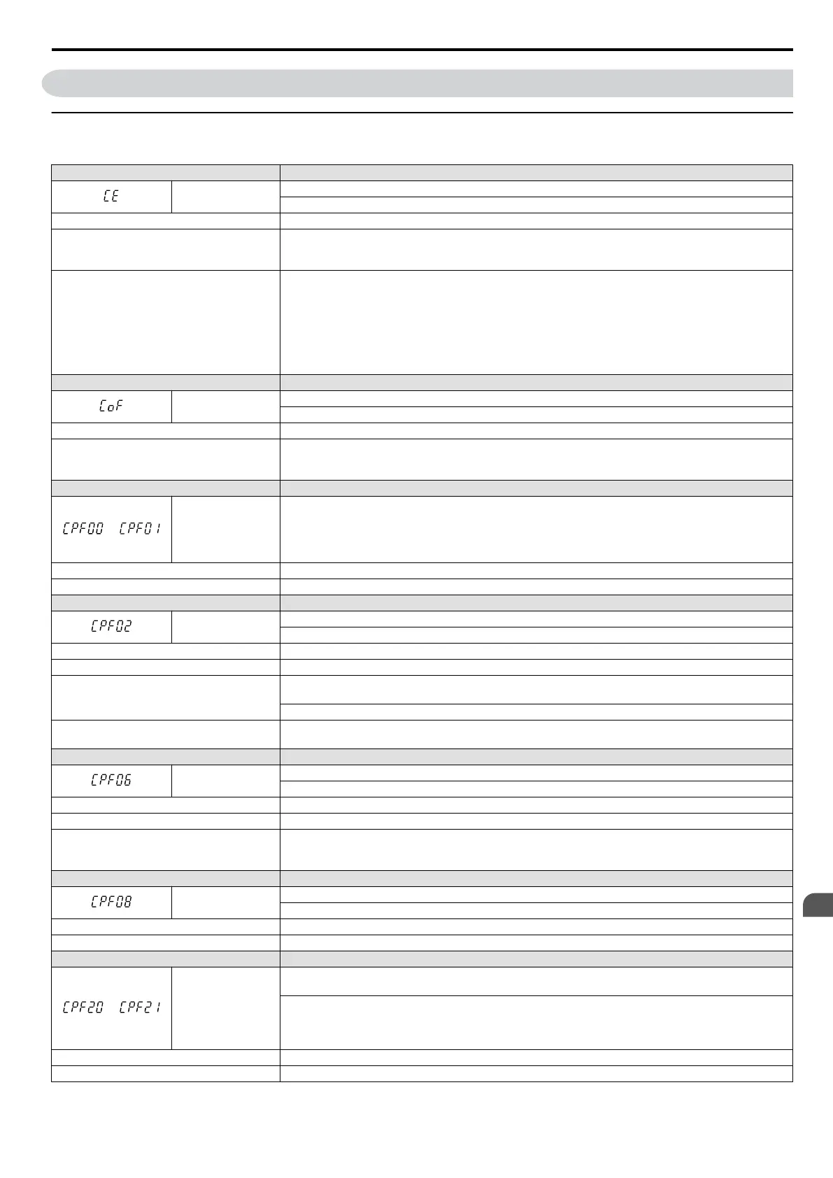
Table 6.7 Detailed Fault Displays, Causes and Possible Solutions
LED Operator Display Fault Name
CE
MEMOBUS/Modbus Communication Error
No data was received for longer than 2 seconds.
Cause Possible Solution
Faulty communications wiring, or a short
circuit exists.
• Check for faulty wiring.
• Correct the wiring.
• Check for loose wiring and short circuits. Repair as needed.
A communications data error occurred due to
noise.
• Check the various options available to minimize the effects of noise.
• Counteract noise in control circuit, main circuit, and ground wiring.
• Use OYMC-recommended cables, or another type of shielded line. Ground the shield on the
controller side or on the drive input power side.
• Ensure that other equipment such as switches or relays do not cause noise and use surge suppressors
if required.
• Separate all wiring for communications devices from drive input power lines. Install a noise filter
to the input side of the drive input power.
LED Operator Display Fault Name
CoF
Current Offset Fault
There is a problem with the current detection circuit.
Cause Possible Solution
While the drive automatically adjusted the
current offset, the calculated value exceeded
the allowable setting range.
Replace the drive.
LED Operator Display Fault Name
or
CPF00 or CPF01
CPF11 – RAM Fault
CPF12 – Problem with the ROM (FLASH memory)
CPF14 – CPU error (CPU operates incorrectly due to noise, etc.)
CPF17 – A timing error occurred during an internal process
CPF18 – CPU error (CPU operates incorrectly due to noise, etc.)
Cause Possible Solution
Hardware is damaged. Replace the drive.
LED Operator Display Fault Name
CPF02
A/D Conversion Error
An A/D conversion error occurred.
Cause Possible Solution
Control circuit is damaged. Cycle power to the drive. If the problem continues, replace the drive.
Control circuit terminals have shorted out
(+V, AC).
• Check for wiring errors along the control circuit terminals.
• Correct the wiring.
Check the resistance of the speed potentiometer and related wiring.
Control terminal input current has exceeded
allowable levels.
• Check the input current.
• Reduce the current input to control circuit terminal (+V) to 20 mA.
LED Operator Display Fault Name
CPF06
EEPROM Data Error
There is an error in the data saved to EEPROM.
Cause Possible Solution
Control circuit is damaged. Cycle power to the drive. If the problem continues, replace the drive.
The power supply was switched off when
parameters were written (e.g., using an option
unit).
Reinitialize the drive (A1-03).
LED Operator Display Fault Name
CPF08
EEPROM Communication Fault
EEPROM communications are not functioning properly.
Cause Possible Solution
Control circuit is damaged. Cycle power to the drive. If the problem persists, replace the drive.
LED Operator Display Fault Name
or
CPF20 or CPF21
One of the following faults occurred: RAM fault, FLASH memory error, watchdog circuit exception,
clock error
• RAM fault.
• FLASH memory error (ROM error).
• Watchdog circuit exception (self-diagnostic error).
• Clock error.
Cause Possible Solution
Hardware is damaged. Replace the drive.
6.4 Fault Detection
SIEP C710606 33A OYMC AC Drive – J1000 User Manual
123
6
Troubleshooting

 Loading...


