LED Operator Display Fault Name
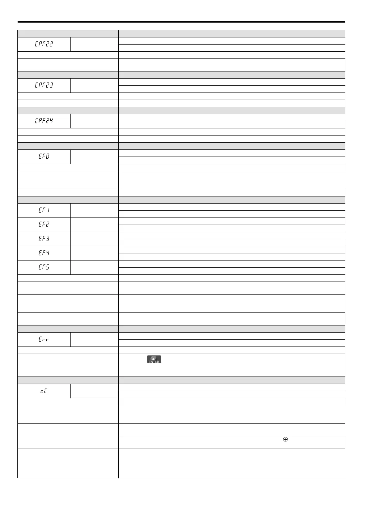
CPF22
A/D Conversion Fault
A/D conversion error.
Cause Possible Solution
Control circuit is damaged.
• Cycle power to the drive. Refer to Diagnosing and Resetting Faults on page 133.
• If the problem continues, replace the drive.
LED Operator Display Fault Name
CPF23
PWM Feedback Fault
PWM feedback error.
Cause Possible Solution
Hardware is damaged. Replace the drive.
LED Operator Display Fault Name
CPF24
Drive Capacity Signal Fault
Entered a capacity that does not exist. (Checked when the drive is powered up.)
Cause Possible Solution
Hardware is damaged. Replace the drive.
LED Operator Display Fault Name
EF0
MEMOBUS/Modbus Communication External Fault
An external fault condition is present.
Cause Possible Solution
An external fault was received from the PLC
with other than H5-04 = 3 “alarm only” (the
drive continued to run after external fault).
• Remove the cause of the external fault.
• Remove the external fault input from the PLC.
Problem with the PLC program. Check the PLC program and correct problems.
LED Operator Display Fault Name
EF1
External Fault (input terminal S1)
External fault at multi-function input terminal S1.
EF2
External Fault (input terminal S2)
External fault at multi-function input terminal S2.
EF3
External Fault (input terminal S3)
External fault at multi-function input terminal S3.
EF4
External Fault (input terminal S4)
External fault at multi-function input terminal S4.
EF5
External Fault (input terminal S5)
External fault at multi-function input terminal S5.
Cause Possible Solution
An external device has tripped an alarm
function.
Remove the cause of the external fault and reset the fault.
Wiring is incorrect.
• Ensure the signal lines have been connected properly to the terminals assigned for external fault
detection (H1- = 20 to 2F).
• Reconnect the signal line.
Incorrect setting of multi-function contact
inputs.
•
Check if the unused terminals set for H1- = 20 to 2F (External Fault).
•
Change the terminal settings.
LED Operator Display Fault Name
Err
EEPROM Write Error
Data does not match the EEPROM being written to.
Cause Possible Solution
-
•
Press the button.
•
Correct the parameter settings.
• Cycle power to the drive. Refer to Diagnosing and Resetting Faults on page 133.
LED Operator Display Fault Name
oC
Overcurrent
Drive sensors have detected an output current greater than the specified overcurrent level.
Cause Possible Solution
The motor has been damaged due to
overheating or the motor insulation is
damaged.
• Check the insulation resistance.
• Replace the motor.
One of the motor cables has shorted out or
there is a grounding problem.
• Check the motor cables.
• Remove the short circuit and power the drive back up.
• Check the resistance between the motor cables and the ground terminal .
• Replace damaged cables.
The load is too heavy.
• Measure the current flowing into the motor.
• Replace the drive with a larger capacity unit if the current value exceeds the rated current of the
drive.
• Determine if there is sudden fluctuation in the current level.
• Reduce the load to avoid sudden changes in the current level or switch to a larger drive.
6.4 Fault Detection
124
SIEP C710606 33A OYMC AC Drive – J1000 User Manual