5.4 d: Reference Settings
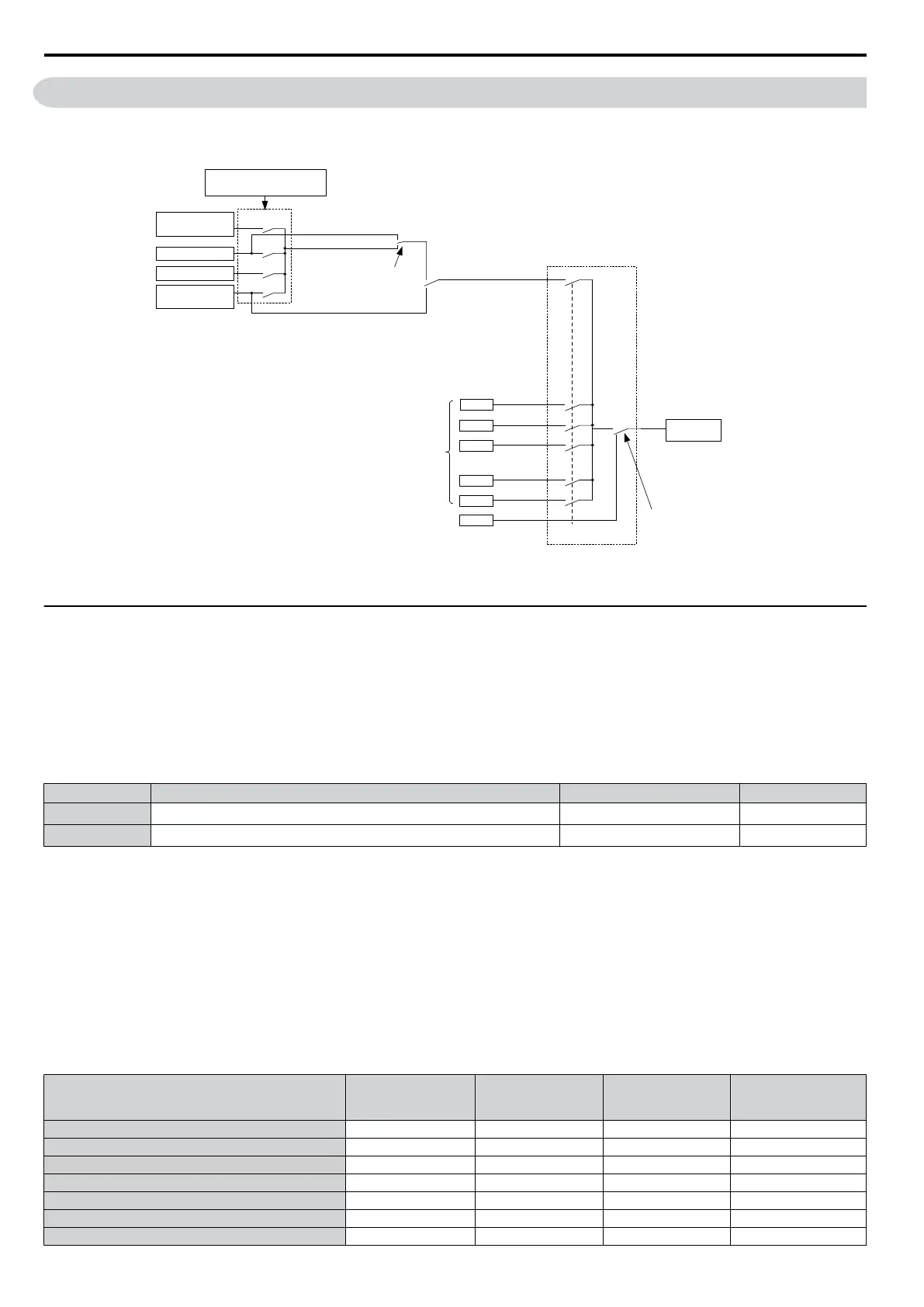
The drive offers various ways of entering the frequency reference. The figure below gives an overview of the reference
input, selections, and priorities.
MS 2
MS 3
MS 4
MS 7
MS 8
Jog
d1-03
d1-04
d1-07
d1-08
d1-17
d1-02
REMOTE
LOCAL
MS 1
0
1
ComRef
=3
=2
=1
=0
0
1
Digital Input
H1- = 2
MEMOBUS comm.
d1-01
(Freq.Ref 1)
b1-01
(Freq. Reference Source 1)
Option Card
Digital Input (H1-)
Jog Reference (=6)
Frequency
Reference
2 through 8
Jog Frequency
Multi-Step Speed
Terminal
A1
Frequency
Reference
Figure 5.8 Frequency Reference Setting Hierarchy
u
d1: Frequency Reference
n
d1-01 to d1-08, d1-17: Frequency Reference 1 to 8 and Jog Reference
Up
to 9 preset references (including Jog reference) can be programmed in the drive. The references can be switched during
Run by digital inputs. The acceleration/deceleration to the new reference is performed using the active acceleration/
deceleration time.
The Jog frequency must be selected by a separate digital input and has priority over the references 1 to 8.
Multi-speed reference 1 can be provided by analog input A1.
No. Parameter Name Setting Range Default
d1-01 to d1-08 Frequency Reference 1 to 8
0.00 to 400.00 Hz
<1>
0.00 Hz
d1-17 Jog Frequency Reference
0.00 to 400.00 Hz
<1>
6.00 Hz
<1> The upper limit is determined by the maximum output frequency (E1-04) and upper limit for the frequency reference (d2-01).
Multi-Step Speed Selection
Depending on how many speeds are used, some digital inputs have to be programmed for Multi-Step Speed Selection 1,
2, 3 and 4 (H1- = 3, 4, 5). For the Jog reference a digital input must be set to H1- = 6.
Notes on using analog inputs as multi-speed 1 and 2:
• If
the frequency reference source is assigned to analog input A1 (b1-01 = 1), then this input will be used for Frequency
Reference 1 instead of d1-01. If the reference source is assigned to the digital operator (b1-01 = 0), then d1-01 will be
used as Frequency Reference 1.
The different speed references can be selected as shown in Table 5.9. Figure 5.9 illustrates the multi-step speed selection.
Table 5.9 Multi-Step Speed Reference and Terminal Switch Combinations
Reference
Multi-Step
Speed
H1- = 3
Multi-Step
Speed 2
H1- = 4
Multi-Step
Speed 3
H1- = 5
Jog Reference
H1- = 6
Frequency Reference 1 (d1-01/A1) OFF OFF OFF OFF
Frequency Reference 2 (d1-02) ON OFF OFF OFF
Frequency Reference 3 (d1-03) OFF ON OFF OFF
Frequency Reference 4 (d1-04) ON ON OFF OFF
Frequency Reference 5 (d1-05) OFF OFF ON OFF
Frequency Reference 6 (d1-06) ON OFF ON OFF
Frequency Reference 7 (d1-07) OFF ON ON OFF
5.4 d: Reference Settings
82
SIEP C710606 33A OYMC AC Drive – J1000 User Manual