No. Name Description Range Def. Mode
Addr.
Hex
Pg.
o4: Maintenance Period
Use o4 parameters to perform maintenance.
o4-01
Accumulated
Operation Time
Setting
Sets the value for the cumulative operation time of the drive in units
of 10 h.
0 to 9999 0 O 50B 114
o4-02
Accumulated
Operation Time
Selection
Determines, how the cumulative operation time (U4-01) is counted.
0: Logs power-on time
1: Logs operation time when the drive output is active (output
operation time).
0, 1 0 O 50C 114
o4-03
Cooling Fan
Operation Time
Setting
Sets the value of the fan operation time in units of 10 h. 0 to 9999 0 O 50E 114
o4-05
Capacitor
Maintenance
Setting
Sets the value of the capacitor maintenance time monitor U4-05. 0 to 150 0% O 51D 114
o4-07
Soft Charge
Bypass Relay
Maintenance
Setting
Sets the value of the Soft Charge Bypass Relay Maintenance
monitor U4-06.
0 to 150 0% O 523 114
o4-09
IGBT
Maintenance
Setting
Sets the value of the IGBT Maintenance monitor U4-07. 0 to 150 0% O 525 114
o4-11
U2 Initialize
Selection
Selects if U2- (Fault History) monitors are reset at drive
initialization.
0: Saves the fault monitor data
1: Resets the fault monitor data
0, 1 0 O 510 115
<12> Default setting value is dependent on parameter o2-04, Drive Model Selection.
<22>
Parameter can be changed during run.
u
U: Monitors
Monitor parameters allow the user to view drive status, fault information, and other information about drive operation.
No. Name Description
Analog Output
Level
Unit Mode
Addr.
Hex
U1: Operation Status Monitors
Use U1 monitors to display the operation status of the drive.
U1-01
Frequency
Reference
Monitors the frequency 10 V: Max frequency 0.01 Hz O 40
U1-02 Output Frequency
Displays the output frequency. Display units are determined by
o1-03.
10 V: Max frequency 0.01 Hz O 41
U1-03 Output Current Displays the output current.
10 V: Drive rated
current
0.01A O 42
U1-06
Output Voltage
Reference
Displays the output voltage.
10 V: 200 Vrms (400
Vrms)
0.1 V O 45
U1-07 DC Bus Voltage Displays the DC bus voltage. 10 V: 400 V (800 V) 1 V O 46
U1-10
Input Terminal
Status
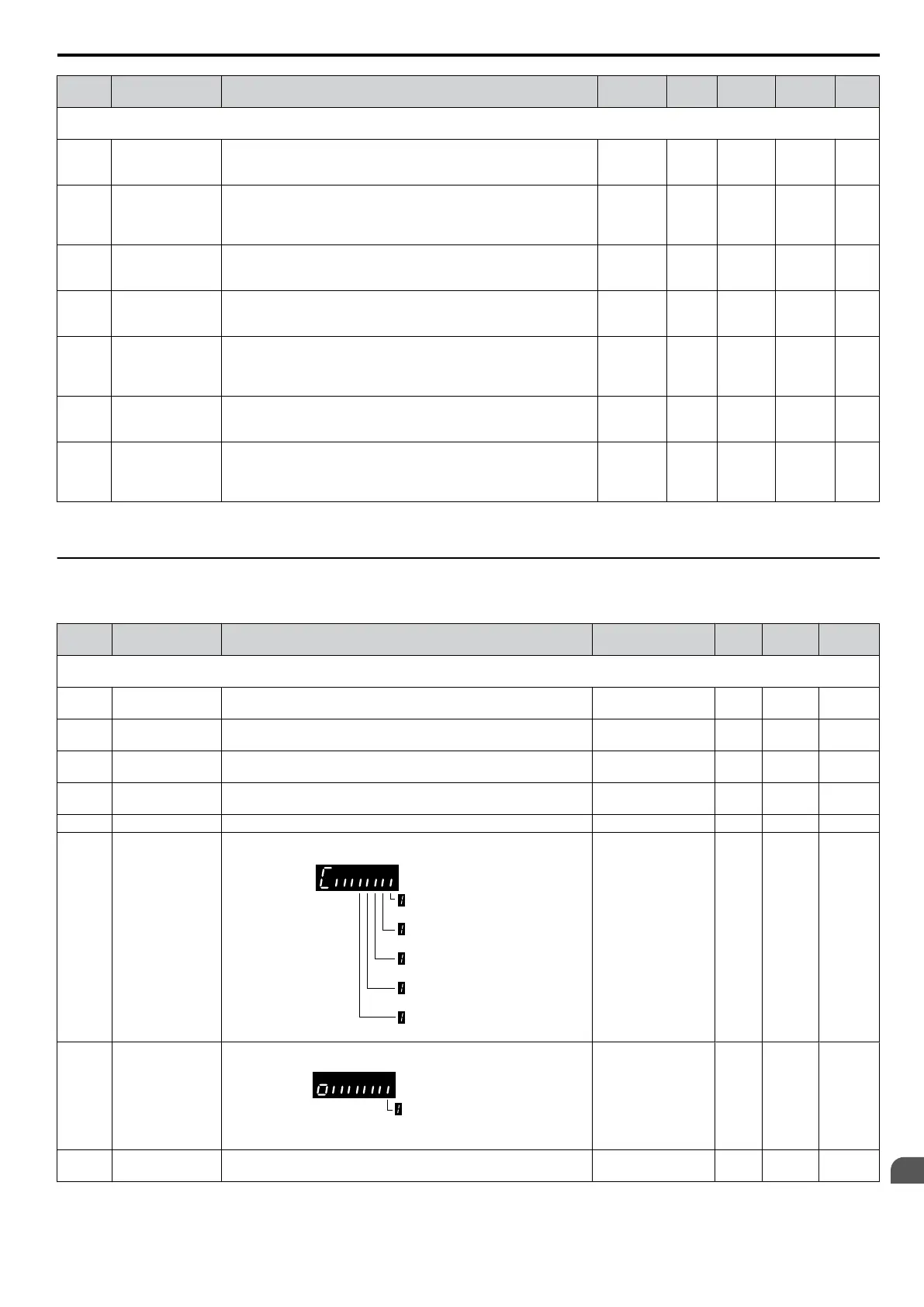
Displays the input terminal status.
Digital input terminal
S1 enabled
Digital input terminal
S2 enabled
Digital input terminal
S3 enabled
Digital input terminal
S4 enabled
Digital input terminal
S5 enabled
No output signal
available
– O 49
U1-11
Output Terminal
Status
Displays the output terminal status.
Multi-Function
Digital Output (fault)
(terminal MA/MB-MC)
No output signal
available
– O 4A
U1-13
Terminal Input
Level
Displays analog input A1 level: 100% when input is 10 V or 20
mA.
10 V/20 mA: 100% 0.1% O 4E
B.2 Parameter Table
SIEP C710606 33A OYMC AC Drive – J1000 User Manual
181
B
Parameter List