LD Cart Transporter User's Guide, 14766-000 Rev B
Page 96 of 190
Chapter 6: Connectivity
The maximum output current of each analog output is 10 mA. Exceeding the maximum
output current will result in damage to the analog output module.
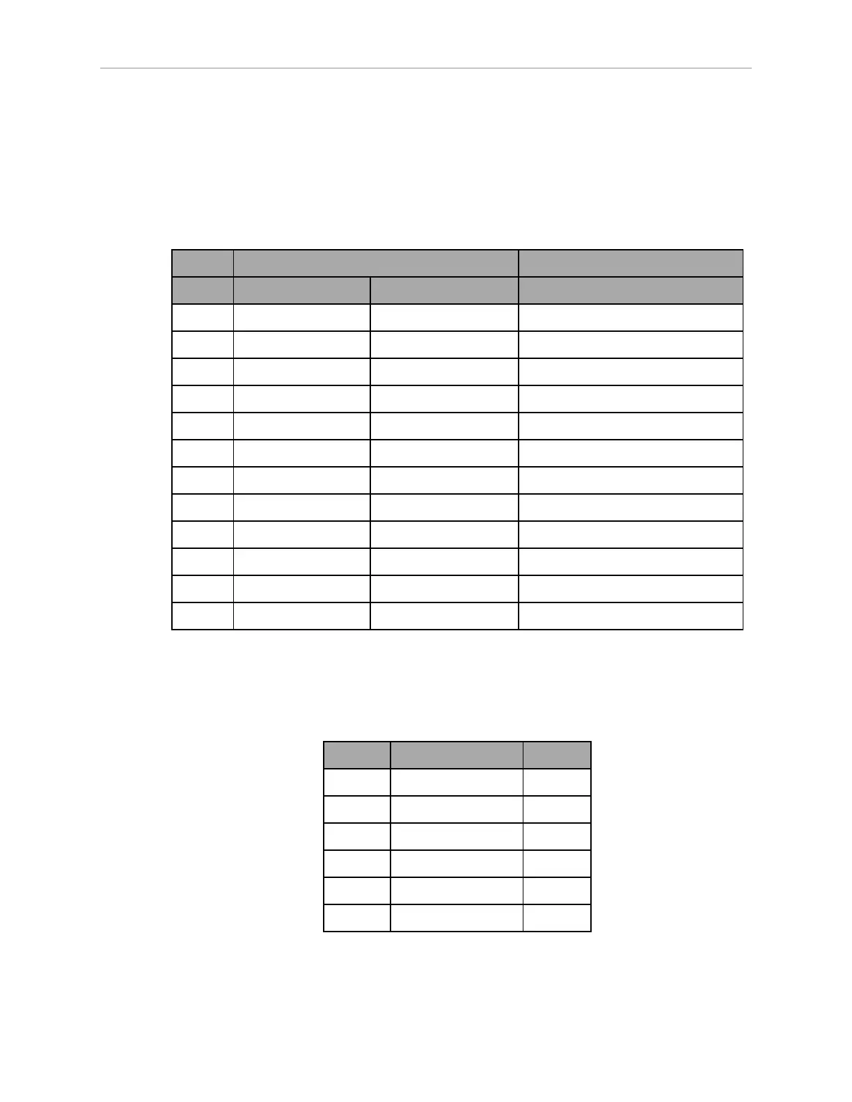
Aux Sensors
Connector type HDB15M
Use Side (vertical) and low sensing (foot)lasers
Designation
Pin No. Hardware Software Notes
1 RS232_VERT1_TXD /dev/ttyUSB5
2 RS232_VERT2_TXD /dev/ttyUSB6
3 RS232_FOOT_TXD /dev/ttyUSB7
4 5V_SW1 USB_1_and_2_Power 5 V @ 1 A (shared with USB port 1)
5, 10 SW_20V_VERT Vertical_Laser_Power 20 V @ 300 mA
6, 7, 8 GND
9 5V_SW2 USB_1_and_2_Power 5 V @ 1 A (shared with USB port 2)
11 RS232_VERT1_RXD /dev/ttyUSB5
12 RS232_VERT2_RXD /dev/ttyUSB6
13 RS232_FOOT_RXD /dev/ttyUSB7
14 5V_SW3 USB_3_Power 5 V @ 1 A (shared with USB port 3)
15 SW_20V_FOOT Foot_Laser_Power 20 V @ 150 mA
RS232 1 & 2
Connector type DB9M
Use Port 1 and 2, General Use
Pin No. Designation Notes
1, 4, 6, 9 No Connection
2 RS232_USR#_RXD #=1 or 2
3 RS232_USR#_TXD #=1 or 2
5 GND
7 RS232_USR#_RTS #=1 or 2
8 RS232_USR#_CTS #=1 or 2