4-45
Main circuit power supply: Supply DC power as follows: positive voltage to +1 terminal, and ground
to – terminal.
External regeneration resistance terminals: Remove the short bar from between B2 and B3 so that
B1, B2, and B3 are open. (For Servo Drivers without B3, open B1 and B2.)
Make sure input voltage is 120 to 179 V DC for 100 V input type, and 240 to 357 V DC for 200 V input
type.
Note 1. Always set this parameter to 1 when using a DC power supply. If a DC power supply is con-
nected with this parameter set to 0, the regeneration absorption circuit will operate, possibly
damaging the Servo Driver. When changing the setting from 0 to 1, either the main circuit pow-
er supply must be OFF, or the external regeneration resistance terminals must be open.
Note 2. If using a DC power supply, the regeneration absorption circuit inside the Servo Driver will not
operate. The regeneration power returns to the DC power supply, so make sure the DC power
supply can absorb the regeneration power.
Note 3. If using a DC power supply, the residual voltage in the main-circuit power supply is not dis-
charged rapidly when the power is turned OFF. Be sure to mount a discharge circuit on the DC
power supply. Also, check that the charge indicator is not lit before storing the power supply
input when the power supply has been turned OFF (the discharge time for the Servo Driver is
approximately 30 minutes.)
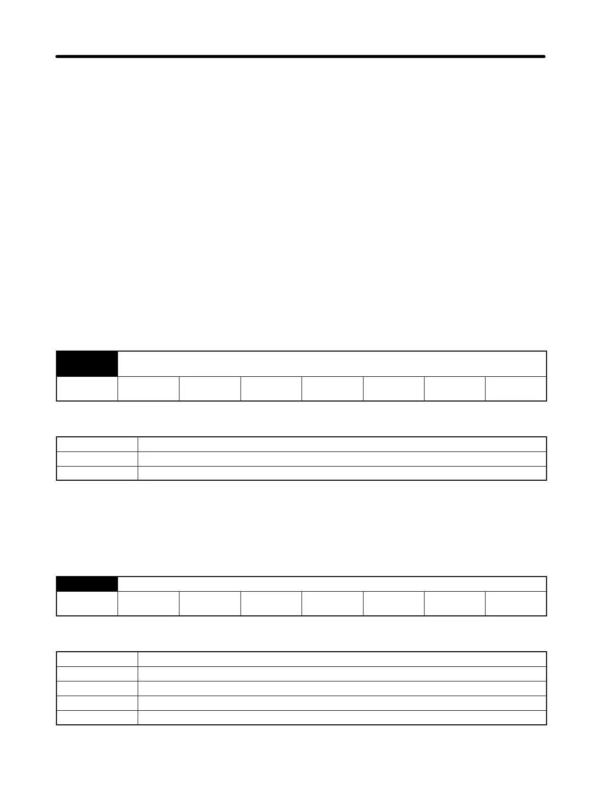
Pn001.3 Function selection application switch 1 –– Warning code output selection (All operation
modes)
Setting
range
0, 1 Unit --- Default
setting
1 Restart
power?
Yes
Setting Explanation
Setting Explanation
0 Only alarm code is output from ALO1, ALO2, and ALO3
1 Both alarm code and warning code are output from ALO1, ALO2, and ALO3
• Select whether the alarm code output will be from outputs ALO1 to ALO3 (CN1-37 to 39) if an alarm
(overload alarm, regeneration overload alarm) occurs.
Note Refer to 5-2 Alarms for warning code details.
D Function Selection Application Switch 2 (Pn002: Default Setting 0000)
Pn002.0 Function selection application switch 2 –– Torque command input change (Position, speed)
Setting
range
0 to 3 Unit --- Default
setting
0 Restart
power?
Yes
Setting Explanation
Setting Explanation
0 Function not used.
1 TREF used as analog torque limit.
2 TREF used as torque feed-forward input.
3 TREF used as analog torque limit when PCL and NCL are ON.
• Set TREF (torque command input) function when using position control and speed control.
Operation Chapter 4
 Loading...


