4-48
Note 1. Displays status without offset adjustment and scaling changes. (Perform offset adjustment
and scaling changes using System Check Mode.)
Note 2. The maximum analog monitor output voltage is 8 V. Exceeding this voltage may result in a
wrong output.
Note 3. Analog monitor output accuracy is approximately 15%.
Pn003.2 Function selection application switch 2 –– Not used.
Setting
range
--- Unit --- Default
setting
0 Restart
power?
No
Note Do not change setting.
Pn003.3 Function selection application switch 2 –– Not used.
Setting
range
--- Unit --- Default
setting
0 Restart
power?
No
Note Do not change setting.
D Unused Parameters (Pn004 and Pn005)
Pn004 Not used.
Setting
range
--- Unit --- Default
setting
0000 Restart
power?
No
Note Do not change setting.
Pn005 Not used.
Setting
range
--- Unit --- Default
setting
0000 Restart
power?
No
Note Do not change setting.
H Gain Parameters (From Pn100)
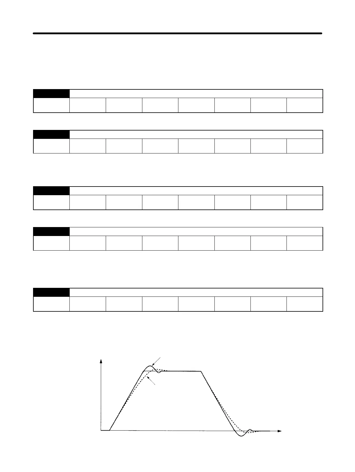
Pn100 Speed loop gain (Position, speed, internally-set speed control)
Setting
range
1 to 2000 Unit Hz Default
setting
80 Restart
power?
No
• This gain adjusts the speed loop response.
• Increase the setting (i.e., increase the gain) to raise servo rigidity. Generally, the greater the inertia
ratio, the higher the setting. There is a risk of oscillation, however, if the gain is too high.
Servomotor
speed (speed
monitor)
Overshoots when speed loop gain is
high. (Oscillates when gain is too high.)
When speed loop gain is low.
Time
Operation Chapter 4
 Loading...


