4-50
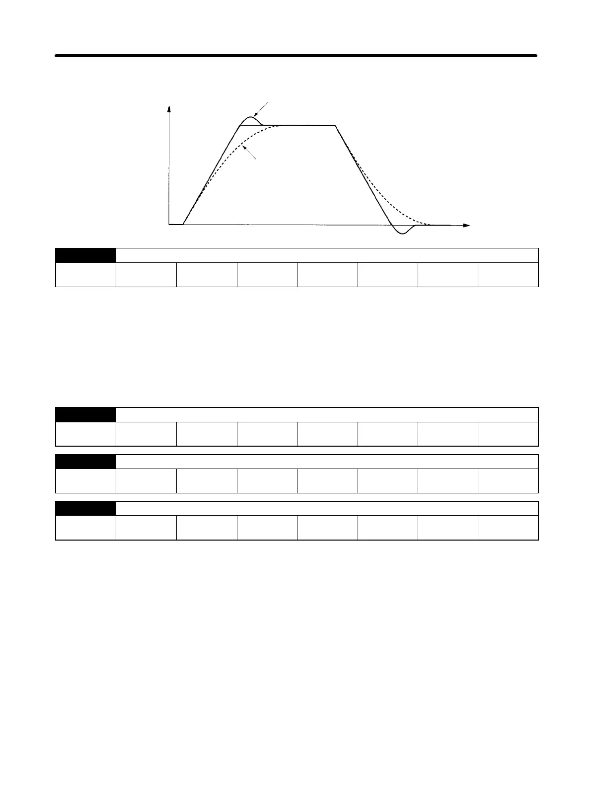
When the position loop gain is manipulated, the response is as shown in the diagram below.
Servomotor
speed
Time
When position loop gain is low
When position loop gain is high
Pn103 Inertia ratio (Position, speed, internally-set speed control)
Setting
range
0 to 20000 Unit % Default
setting
300 Restart
power?
No
• Set the mechanical system inertia (load inertia for Servomotor shaft conversion) using the ratio (%) of
the Servomotor rotor inertia. If the inertia ratio is set incorrectly, the Pn100 (speed loop gain) value will
also be incorrect.
• This parameter is the initial online auto-tuning value. After performing online auto-tuning, the correct
value will be written to Pn103 if the tuning results are saved. Refer to 4-7-1 Online Auto-tuning for
details.
Note The setting range is 0 to 10,000 when the Servo Driver software version is “r.0014” or earlier.
Pn104 No. 2 speed loop gain (Position, speed, internally-set speed control)
Setting
range
1 to 2000 Unit Hz Default
setting
80 Restart
power?
No
Pn105 No. 2 speed loop integral time constant (Position, speed, internally-set speed control)
Setting
range
15 to 51200 Unit x 0.01 ms Default
setting
2000 Restart
power?
No
Pn106 No. 2 position loop gain (Position, speed with position lock)
Setting
range
1 to 2000 Unit 1/s Default
setting
40 Restart
power?
No
• These parameters are gain and time constants selected when using gain switching under the follow-
ing conditions.
S When GSEL (gain switching input) is used.
A terminal must be allocated using Pn50d.2 (input signal selection 4 –– GSEL (gain switching)
signal input terminal allocation). Refer to 4-8-5 Gain Switching (Position, Speed, Internally-set
Speed Control) for details.
S When automatic gain switching is set and the switching conditions are met.
Pn10b.2 (automatic gain switching selection) must be set. Refer to 4-8-6 Automatic Gain Switch-
ing (Position Control) for details.
• If the mechanical system inertia changes greatly or if you want to change the responsiveness for when
the Servomotor is rotating and when it is stopped, you can achieve the appropriate control by setting
the gain and time constant beforehand for each of these conditions, and then switch according to the
conditions.
Operation Chapter 4
 Loading...


