4-51
• We recommend using Racks on which online auto-tuning cannot be set to be always enabled. Online
auto-tuning cannot be set to be always enabled under the following conditions.
S When using torque feed-forward function.
S When load inertia fluctuates by 200 ms maximum.
S During operations where rotation speed does not exceed 500 r/min., or output torque does not
exceed 50% of the rated torque.
S When external power is constantly applied, as with the vertical axis.
Note 1. Automatic gain switching is enabled for position control only. When position control is not
used, the Servomotor operates using No. 1 gain (Pn100, Pn101, Pn102).
Note 2. When automatic gain switching is used, set No. 1 gain for gain during operation, and set No. 2
gain for gain while stopped.
Note 3. Automatic gain switching and gain switching using GSEL (gain switching input) cannot be
used together. When Pn10b.2 (automatic gain switching selection) is set between 1 and 3,
GSEL switching is disabled.
Note 4. When No. 2 gain is selected, online auto-tuning is normally disabled.
Pn107 Bias rotational speed (Position)
Setting
range
0 to 450 Unit r/min. Default
setting
0 Restart
power?
No
Pn108 Bias addition band (Position)
Setting
range
0 to 250 Unit r/min. Default
setting
7 Restart
power?
No
• These two parameters set the position control bias.
• This function shortens the positioning time by adding the number of bias rotations to the speed com-
mand (i.e., commands to the speed control loop).
• When the deviation counter residual pulses exceed the Pn108 (bias addition band) setting, the speed
set in Pn107 (bias rotational speed) is added to the speed command, and when they are within the
limits for Pn108, it stops being added.
Note 1. Set Pn107 to 0 if not using bias function.
Note 2. If the bias rotation speed is too great, the Servomotor operation may become unstable. The
optimum value will vary depending on the load, gain, and bias addition range, so check and
adjust the Servomotor response. (Gradually increase the value, starting from Pn107 = 0.)
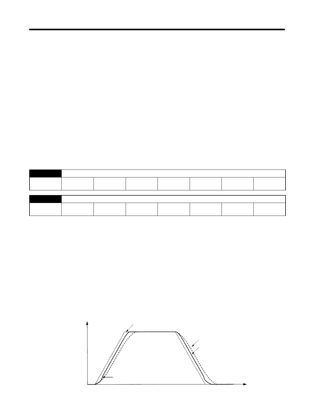
Bias function operation
Speed command
(command pulse fre-
quency)
Pn107 added to speed
command when residual
pulses exceed Pn108
Time
Servomotor
speed
(speed monitor)
Bias function not used.
Bias function used.
Operation Chapter 4
 Loading...


