6-6
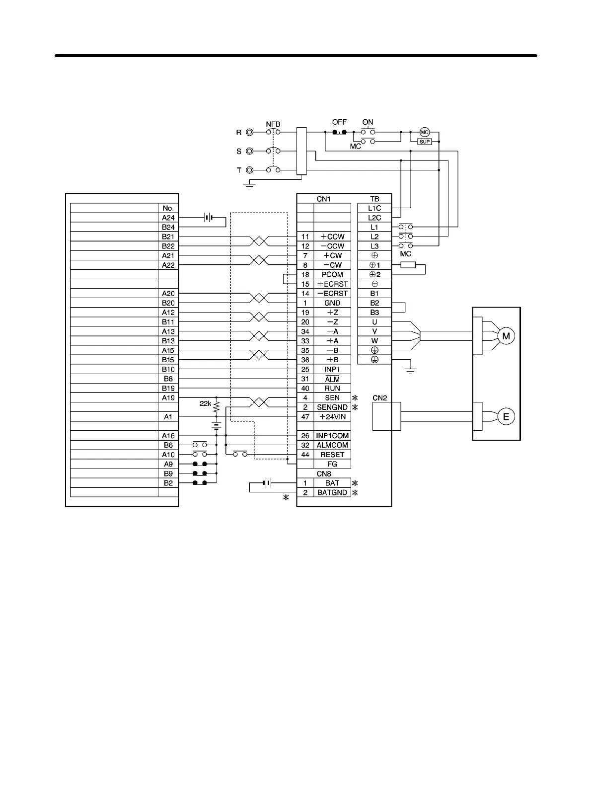
H Connection Example 5: Connecting to 3F88M-DRT141 DeviceNet
Single-axis Positioner
Encoder Cable
R88A-CRWj
R88A-CRWjR
Class-3 ground
Main circuit power supply
3F88M-DRT141
3-phase 200/230 V AC 50/60Hz
Main circuit contact
Surge killer
DC reactor
Red
White
Blue
Green/
Yellow
Contents
24 V DC
24 V DC
Battery
2.8 to 4.5 V DC
+24-V power supply (power supply for Unit)
VDD ground (power supply for Unit)
IN15 (driver alarm)
OUT06 (RUN ON/OFF output)
CCW pulse (+)
CCW pulse (–)
CW pulse (+)
CW pulse (–)
Deviation counter reset (–)
Deviation counter reset (+)
+5-V power supply for origin
Origin sensor input
+5-V A-phase power supply
A-phase input
+5-V B-phase power supply
B-phase input
IN19 (driver in-position)
OUT05 (absolute value read)
+24-V power supply (for general-purpose input)
Output common
IN11 (RUN ON/OFF input)
IN18 (origin proximity)
IN16 (+ limit input)
IN17 (– limit input)
IN03 (emergency stop)
Noise filter
R88D-WTj
R88M-Wj
Shell
Power Cable
R88A-CAWj
R88A-CAWjR
Note 1. The example shows a three-phase, 200-V AC input to the Servo Driver for the main circuit
power supply. Be sure to provide a power supply and wiring conforming to the power supply
specifications for the Servo Driver in use.
Note 2. Incorrect signal wiring can cause damage to Units and the Servo Driver.
Note 3. Leave unused signal lines open and do not wire them.
Note 4. The diode recommended for surge absorption is the ERB44-02 (Fuji Electric).
Note 5. Make the setting so that the Servo can be turned ON and OFF with the RUN signal.
Note 6. General-purpose I/O is one allocation example. The emergency stop, limit input, and driver
alarm contacts are NC and the driver in-position, origin proximity, RUN ON/OFF input, RUN
ON/OFF output, and absolute value read contacts are NO.
Note 7. Connect the terminals and wiring marked with an asterisk (*) when using an Absolute Encod-
er.
Note 8. Use command pulse output in the line driver output setting.
Appendix Chapter 6

 Loading...


