Regular Payload Series-Hardware Installation Manual TM5 Series Hardware Version: 3.2 64
5.6 Control Box Power Interface and Robot Interface
5.6.1 Control Box Power Interface
TM5-700 / TM5-900 / TM5X-700 / TM5X-900:
The power cable of the control box has an IEC plug. The local power plug is connected to the IEC plug.
The AC power switch must be in OFF state before plugging in or out the power cable.
TM5M-700/ TM5M-900:
The power cable of the control box has Hirose (HRS) DF60 series connector.
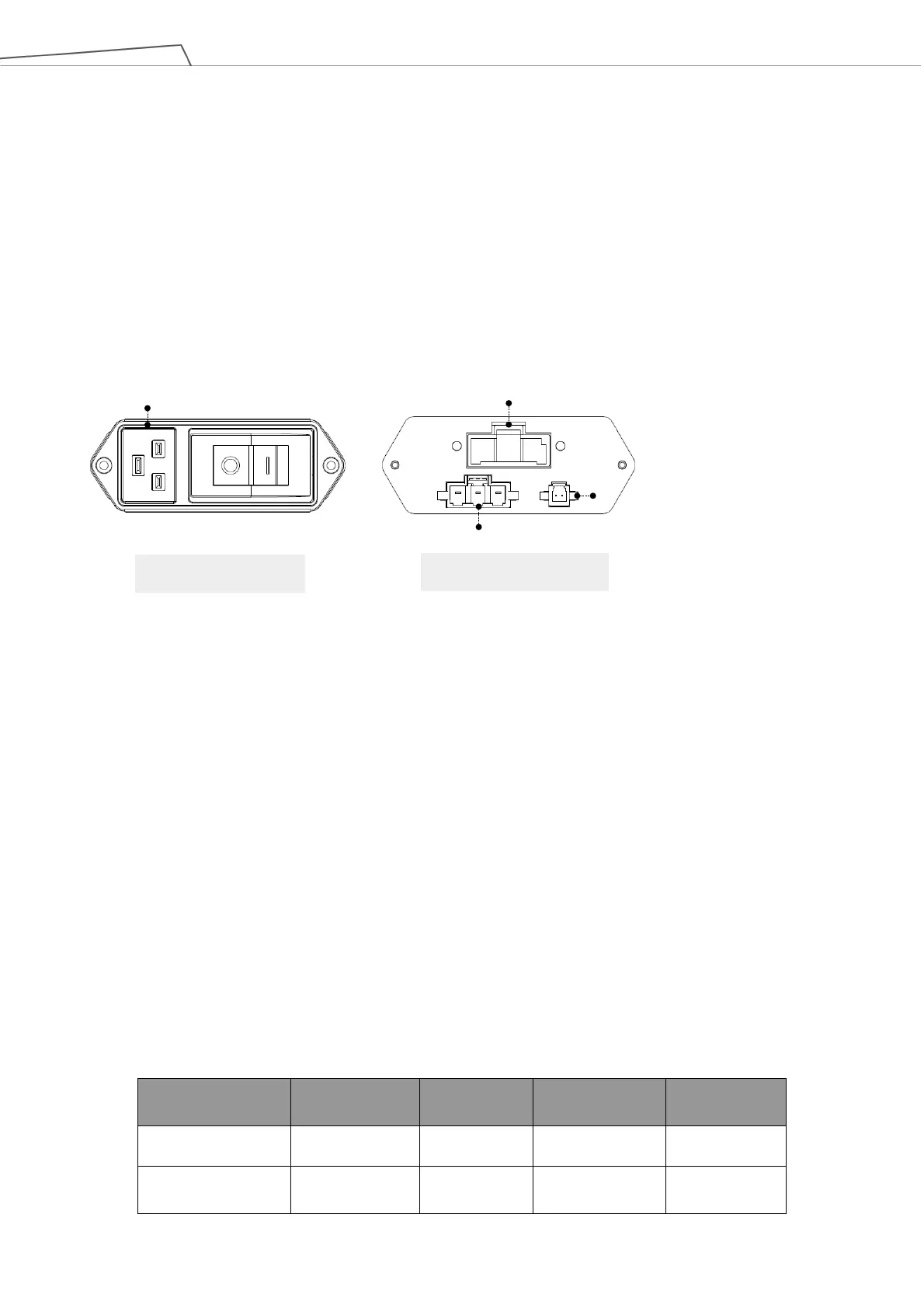
Figure 62: Control Box Power Interfaces
The power supply should be equipped with the following:
• Grounding
• Main fuse
• Residual current device (RCD)
It is recommended to install a master switch on the equipment power supply for robot applications for
servicing and inspection.
Parameters Minimum value Typical value Maximum value Unit
Input voltage 100 - 240 VAC
External mains fuse
- - 15 A
AC Adapter:IEC plug
DC IN Power Connector:( HRS)DF60-3EP-10.16C
DC IN for External Power Supply Connector: Contact the Corporation for
purchasing
External Power Supply Remote Control Connector:Contact the Corporation
for purchasing
External Power Supply Remote Control
DC IN for External Power Supply