Regular Payload Series-Hardware Installation Manual TM5 Series Hardware Version: 3.2 72
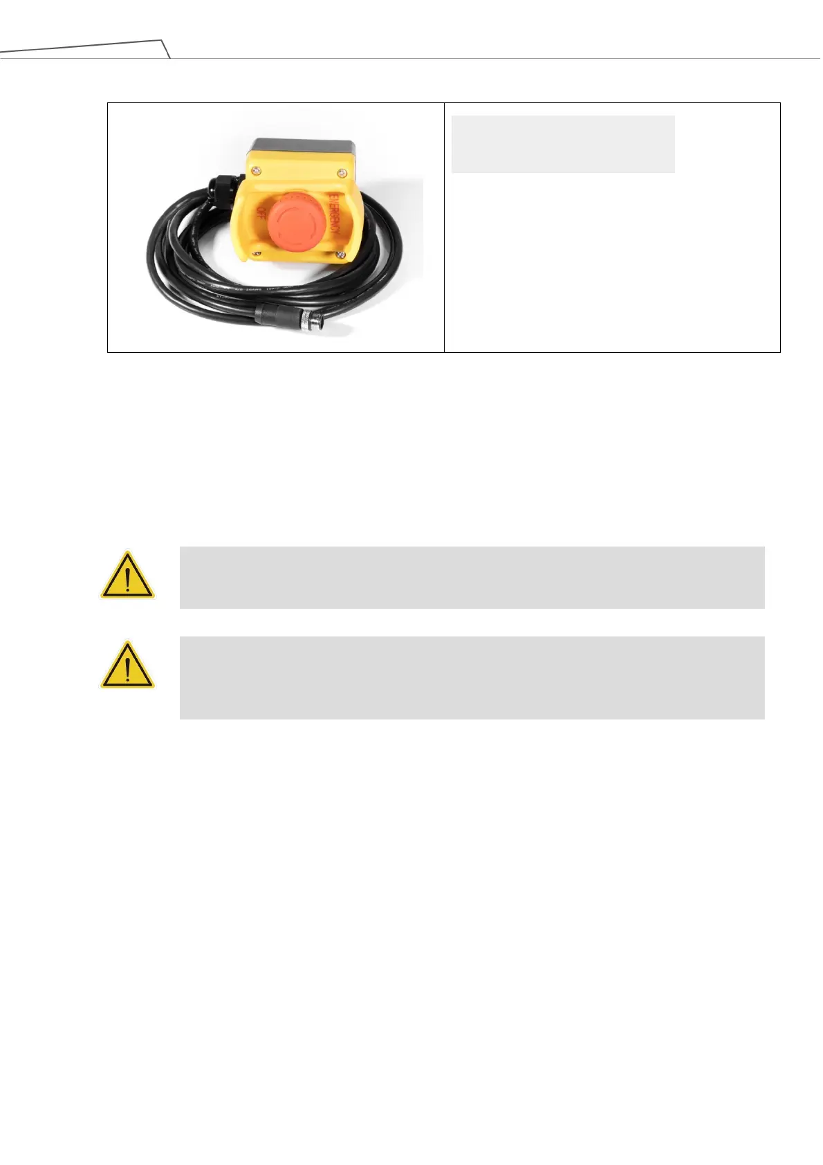
The SEMI Emergency OFF Switch carton contains:
(1 pack)
Cable length: 300 cm
Table 21: The SEMI Emergency OFF Switch Carton Contents
6.4 Installing Your Robot
The TM Robot arm cannot stand independently after being removed from the carton. Therefore, prepare the
mounting base with the corresponding holes as described in 4.2.1.6 Robot Arm Installation, and follow the
instructions below to install the robot.
WARNING:
At the installation site, at least two people should simultaneously perform installation of the
robot; otherwise you risk robot arm damage or personal injury. Do not install the robot alone.
WARNING:
Do not attempt to move any robot links until the robot has been secured in position. Failure to
comply could result in the robot falling and causing either personnel injury or equipment
6.4.1 Remove the Control Box
After checking the contents, remove the contents in order and perform installation.
Control box carton:
Remove the Calibration Plates and TM Landmark
Remove the power cable of the control box
Remove the control box (At least two people should remove the control box from the carton.
Refer the figure below for the correct holding positions.)
Connect the power cable to the control box
Place the control box near the robot base
SEMI Emergency OFF Switch