No. 20S071-01
STC-HD213DV / STC-HD213DV-CS / STC-HD213SDI / STC-HD213SDI-CS /
STC-HD213DVN / STC-HD213DVN-CS / STC-HD213SDIN / STC-HD213SDIN-CS
Product Specifications and User
70/94
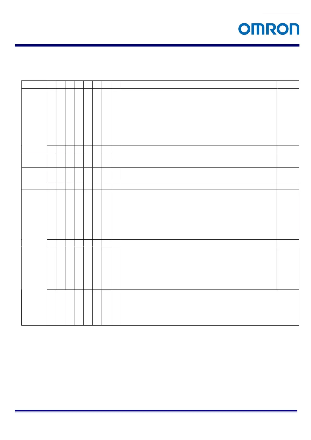
8.4 The uCOM register mapping list
* Please do not change “Reserved data”.
Address
7
6
5
4
3
2
1
0
Descriptions Default
000 X
X
X
User Preset
DSP register setting can save on eight Preset areas.
* When this vale saves to EEPRM, camera starts with saved DSP
mode at power up.
0: Preset 0 1: Preset 1
2: Preset 2 3: Preset 3
4: Preset 4 5: Preset 5
6: Preset 6 7: Preset 7
0
X
X
X
X
X
Reserved -
001 -
00D
X
X
X
X
X
X
X
X
Reserved -
00E X
"Push button" function
0: Disable 1: Enable
1
X
X
X
X
X
X
X
Reserved -
00F X
X
X
UART baud rate
0: 9,600 bps 1: 19,200 bps
2: 38,400 bps 3: 57,000 bps
4: 115,200 bps
* Change to lower baud rate when communication error is
occurred.
2
X
X
X
Reserved -
X
Return data and data length of UART write command
0: Disable.
Return data is including exact same data of write command.
1: Enable.
Return data is excluding data of write command, and data
length is 0.
0
X
UART check sum
0: Disable 1: Enable
* When selecting disable, camera process command even check
sum of send command is not mach.
1

 Loading...


