3-7
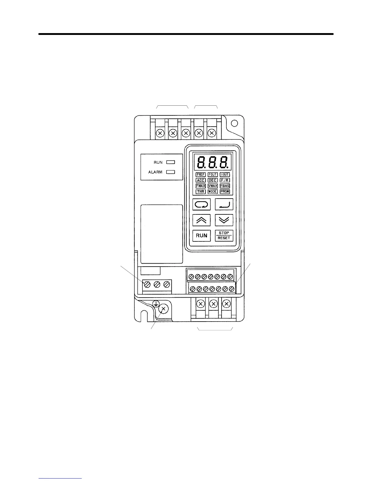
3-2-1 Terminal Blocks
H Name of Each Terminal Block
Main Circuit Terminals (Input)
Power input
terminals
Braking resistor
connection terminals
Control circuit terminals (output)
Ground terminal
Main Circuit Terminals (Output)
Motor output
terminals
Control circuit terminals
(input/output)
MA MB MC
SF SR S1 SC FS FR FC
L1 N/L2 L3 B1 B2
S2 S3 SC AM AC PA PC
UV W
Note This diagram shows an Inverter with all terminal block covers removed.
The standard Inverters are not provided with the S2 to PC terminal block.
Design Chapter 3