3-11
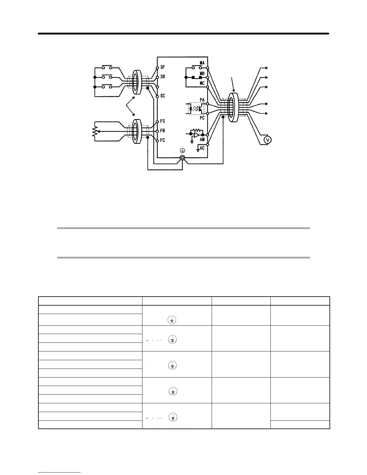
D Control Circuit Terminal Connections
Forward/Stop
Reverse/Stop
Sequence input common
Multi-function input
Clamp
core
Frequency reference adjuster
Frequency reference
power supply (12 V)
Frequency reference
input
Frequency reference
input common
Multi-function contact
output (Contact a)
(Contact b)
Common
Multi-function
photocoupler output
Multi-function
photocoupler output
common
Multi-function analog output
Multi-function analog
output common
Voltmeter
S1 to S3
Clamp core
(2 kΩ, 1/4 W min.)
Note 1. The standard model does not have the S2, S3, PA, PC, AM, or AC terminal.
Note 2. The sequence input and the sequence output can be wired with a single shielded cable.
3-2-2 Wiring Around the Main Circuit
System reliability and noise resistance are affected by the wiring method used. There-
fore, always follow the instructions given below when connecting the Inverter to periph-
eral devices and other parts.
H Wire Size
For the main circuit and ground, always use 600-V polyvinyl chloride (PVC) cables.
If the cable is long and may cause voltage drops, increase the wire size according to the cable length.
Model Terminal symbol Terminal screw Wire size (mm
2
)
3G3EV-A2001(M)-CUE R S T B1 B2
M3.5 0.75 to 2
3G3EV-AB001(M)-CUE
U V W
3G3EV-A2002(M)-CUE
R S T B1 B2 M3.5 0.75 to 2
3G3EV-AB002(M)-CUE
U V W
3G3EV-A4002(M)-CUE