!
!
3-16
If the regenerative energy exceeds the Inverter capacity, overvoltage will be detected in the main circuit.
In such a case, use a Braking Resistor or Braking Resistor Unit.
Note Be sure to create a sequence that will turn OFF the Inverter power supply when resistor over-
heating occurs. When using a Braking Resistor, be sure to install a thermal relay to detect resis-
tor overheating. When using a Braking Resistor Unit, use an error output contact. Otherwise, a
fire may occur.
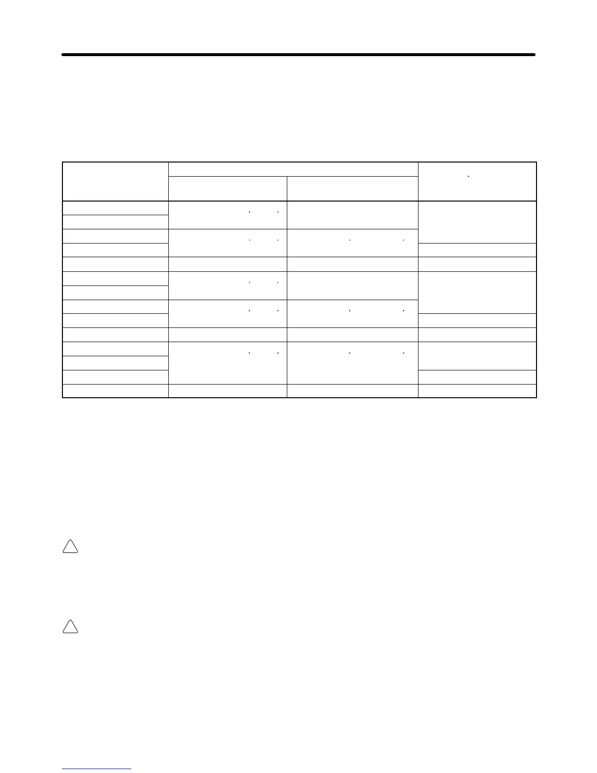
Model 3G3EV-
Model 3G3IV-
Minimum connected
A4007(M)-CUE 510 Ω
A4015(M)-CUE PERF150WJ401 (400 Ω) PLKEB41P5 (400 Ω 260 W) 240 Ω
Note Do not use a Resistor whose resistance is below the minimum connected resistance. Other-
wise, the Inverter will be damaged.
H Wiring on the Output Side of Main Circuit
D Connecting the Terminal Block to the Load
Connect output terminals U, V, and W to motor lead wires U, V, and W, respectively.
D Never Connect Power Supply to Output Terminals
Caution Never connect a power supply to output terminals L1, N/L2, and L3.
If voltage is applied to the output terminals, the internal mechanism of the Inverter
will be damaged.
D Never Short or Ground the Output Terminals
Caution If the output terminals are touched with bare hands or the output wires come into
contact with the Inverter casing, an electric shock or grounding will occur. This is ex-
tremely hazardous. Also, be careful not to short the output wires.
D Do Not Use a Phase Advance Capacitor or LC/RC Noise Filter
Never connect a phase advance capacitor or LC/RC Noise Filter to the output circuit. Doing so may
result in damage to the Inverter or cause other parts to burn.
Design Chapter 3