3-22
To mount the Digital Operator, connect the upper part of the Digital Operator first, and press the Digital
Operator until the internal connector is securely connected.
D Selecting Frequency Reference Input (Current Input)
1. Change of Constant
Set constant n02 for operation mode selection to 4 or 5.
n02 = 4: The Inverter is operated with the Digital Operator while frequency references are pro-
vided as terminal input (current input).
n02 = 5: The Inverter is operated and frequency references are provided through terminals (cur-
rent input).
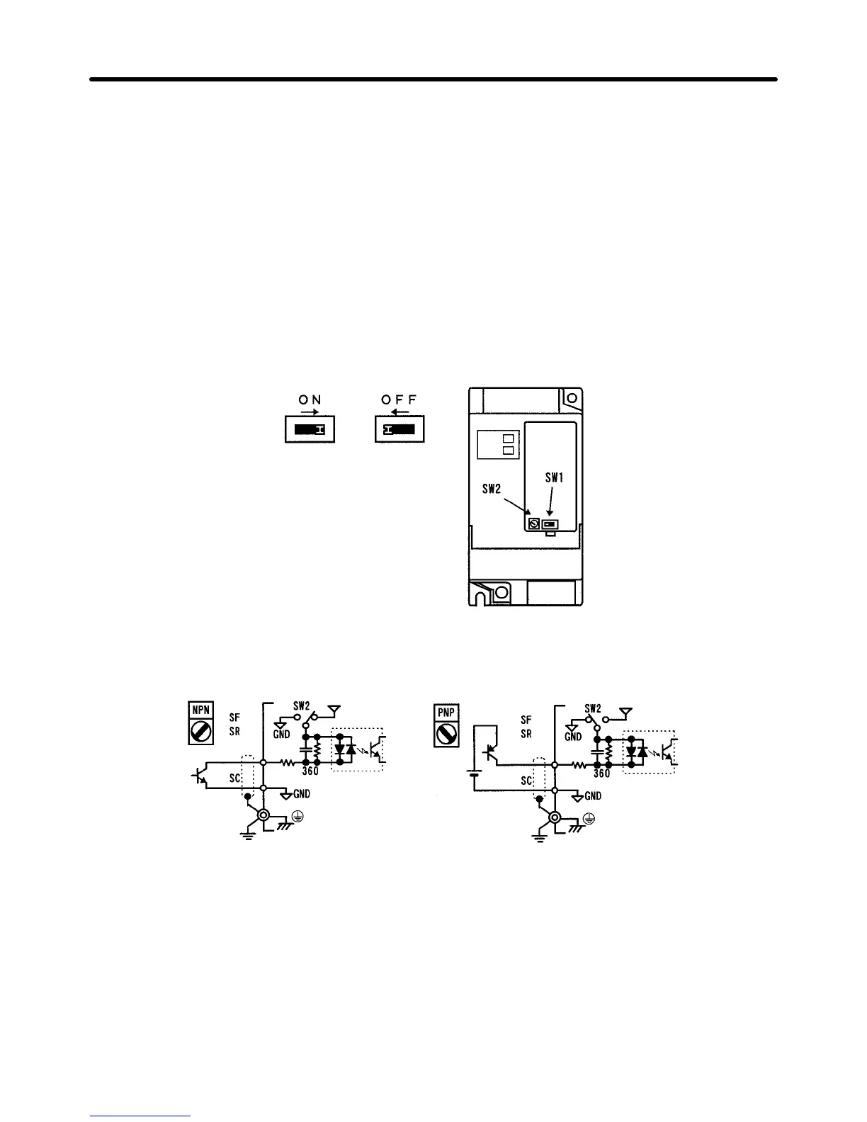
2. SW1 Selector
Set SW1 to ON by sliding SW1 to the right to operate the Inverter with current input.
Sequential Input Selection (NPN/PNP Transistor)
Select NPN or PNP transistor input with SW2.
S1 to S3
24 V
3.3 K
0.1 µ
S1 to S3
24 V
3.3 K
0.1 µ
Design Chapter 3