Appendix AInspection and Maintenance
61
3. While
pushing down the lock lever on the Backplane with a screwdriver
as
shown below, remove the Output Unit.
4. Remove the screw from the top of the Unit (Phillips screwdriver).
5. Detach the case from the Unit (flat-blade screwdriver).
6. Pull
out the printed circuit board. The Relays are placed on the PC boards of
individual Units as shown in the figures below.
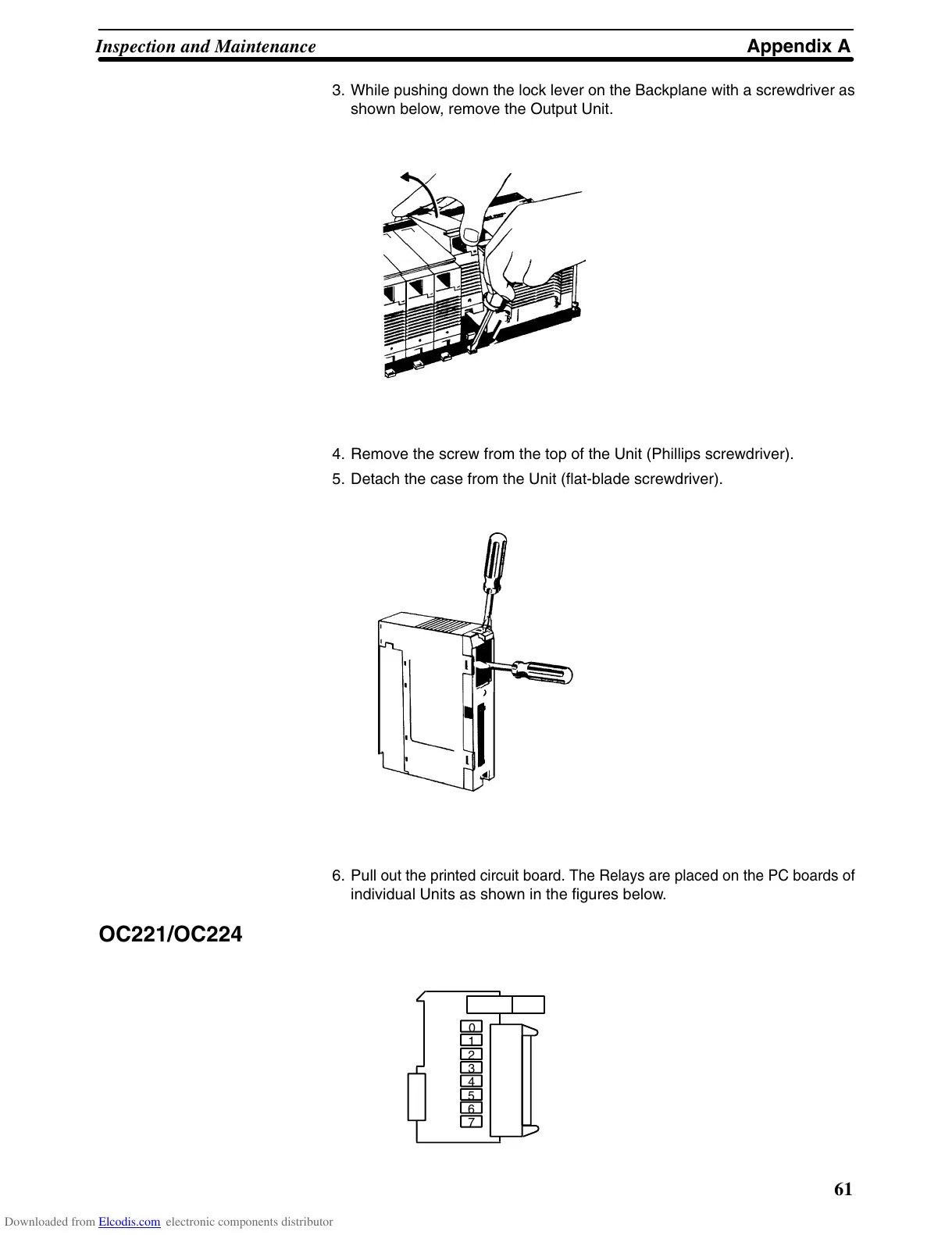
OC221/OC224
1
2
3
4
5
6
7
0
Downloaded from Elcodis.com electronic components distributor