Appendix BSpecifications
147
*Manufacturing Numbers
jjY9
Year: Last digit of calendar year; e.g., 1999→9, 2000→0
Month: 1 to 9 (January to September), X (October), Y (November), Z (December)
Day: 01 to 31
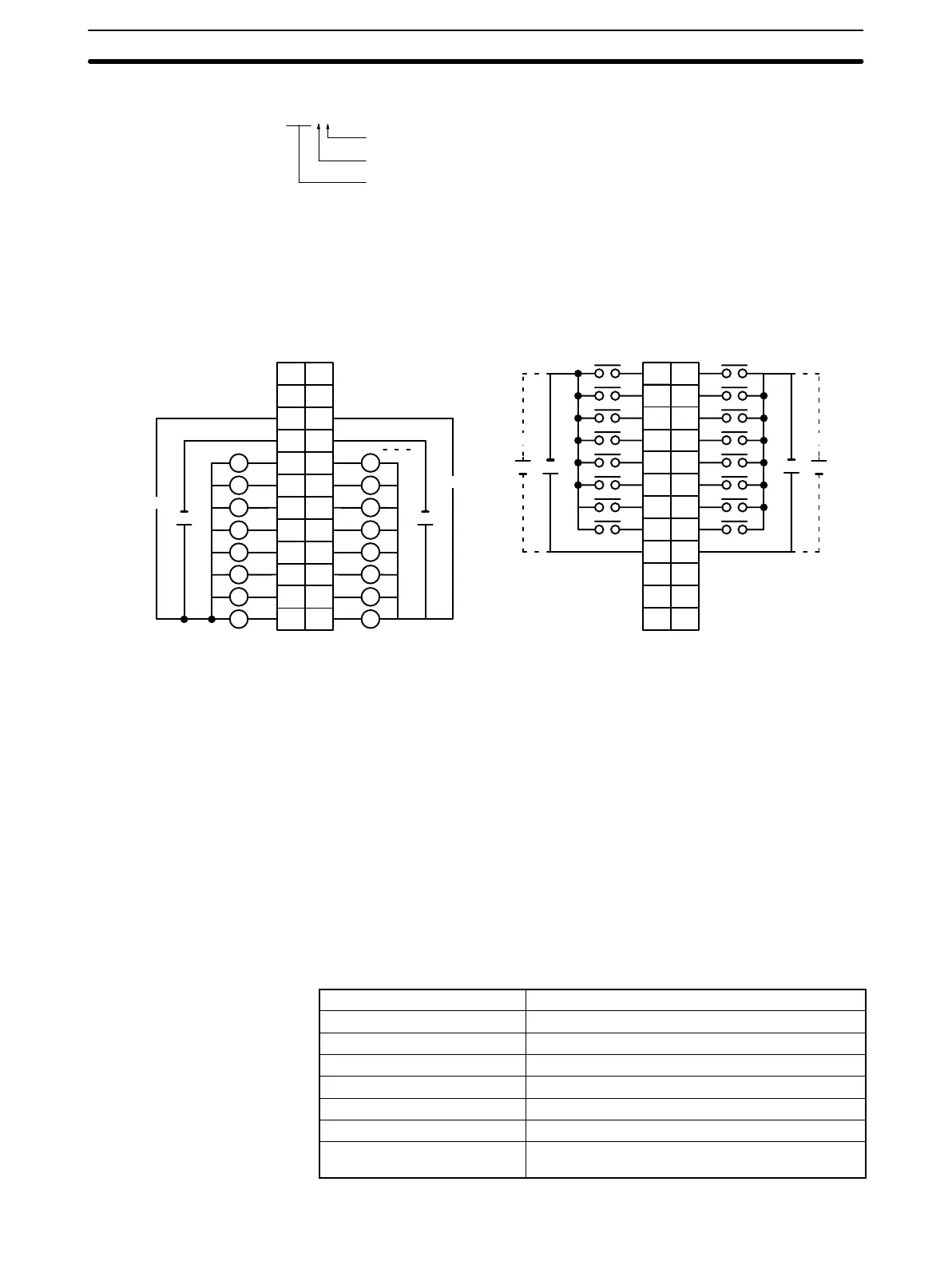
Terminal Connections
I/O word “n”
CN1
I/O word “n+1”
CN2
AB
0
1
1
2
2
3
3
4
4
5
5
6
6
7
7
8
COM2
9
8
9
10
11
12
13
14
15
COM3
+
+
NC
10
NC
11
NC
NC
NC
12
NC
+
24 VDC
1
2
3
4
5
6
7
8
9
10
11
12
+
24 VDC
L
+5 to 24 VDC +5 to 24 VDC
B
1
2
3
4
5
6
7
8
9
0
1
2
3
4
5
6
7
COM0
+
10
NC
11
NC
8
9
10
11
12
13
14
15
COM1
+
NC
12
A
1
2
3
4
5
6
7
8
9
10
11
12
NC
5 to 24 VDC
5 to 24 VDC
L
L
L
L
L
L
L
L
L
L
L
L
L
L
L
Note 1. I/O word “n” is determined by the unit number setting (n = IR 100 + 10 × unit number).
2. The Unit will have 16 static output and16 static input points when pin 1 of it’s DIP switch is OFF.
3. At high temperatures, the number of inputs that can be turned ON simultaneously is limited. Refer to the
graph on page 150 for details.
4. When pin 2 of the Unit’s DIP switch is ON, input points 08 to 15 in connector 2 are high-speed inputs.
5. When wiring output circuits, be sure to use the correct polarity for the external power supplies. Wiring
with incorrect polarity may result in erroneous operation of the load.
24 VDC Input/Transistor Output Unit C200H-MD215
(Used as 128-point Dynamic Input Unit)
Output Specifications (Connector 1)
Max. Switching Capacity 100 mA 24 VDC, 800 mA/common, 1.6 A/Unit
Min. Switching Capacity None
Leakage Current 0.1 mA max.
Residual Voltage 0.7 V max.
ON Response Time 0.2 ms max.
OFF Response Time 0.6 ms max.
Fuses 2 (1 fuse/common; fuses are not user-replacable.)
Power for External Supply 45 mA 5 to 24 VDC±10% min.
(2.8 mA × number of ON outputs)
Artisan Technology Group - Quality Instrumentation ... Guaranteed | (888) 88-SOURCE | www.artisantg.com