64
Component Names and Functions Section 2-1
!Caution Do not connect the 5-V power supply of Pin 6 to any external device other
than an NT-AL001-E Link Adapter. Otherwise, the external device and the
Serial Communications Board or Unit may be damaged.
The following cables are provided for connection to NT-AL001-E Link Adapt-
ers. We recommend that these cables be used.
NT-AL001-E connecting cables: XW2Z-070T-1 (0.7 m)
XW2Z-200T-1 (2 m)
Applicable Connectors
Plug: XM2A-0901 (manufactured by OMRON) or equivalent
Hood: XM2S-0911-E (manufactured by OMRON) or equivalent
One plug and one hood are provided for each port.
Recommended Cables
UL2426 AWG28 × 5P IFS-RVV-SB (UL-approved, Fujikura Ltd.)
AWG28
× 5P IFVV-SB (not UL-approved, Fujikura Ltd.)
UL2426-SB (MA) 5P × 28AWG (7/0.127) (UL-approved, Hitachi Cable, Ltd.)
CO-MA-VV-SB 5P
× 28AWG (7/0.127) (not UL-approved, Hitachi Cable, Ltd.)
Cable length: 15 m max.
RS-422A/485 Port
Note High-speed NT link is only available with Serial Communications Boards/Units
manufactured on or after December 20th, 1999. With earlier models, only
standard NT link is available.
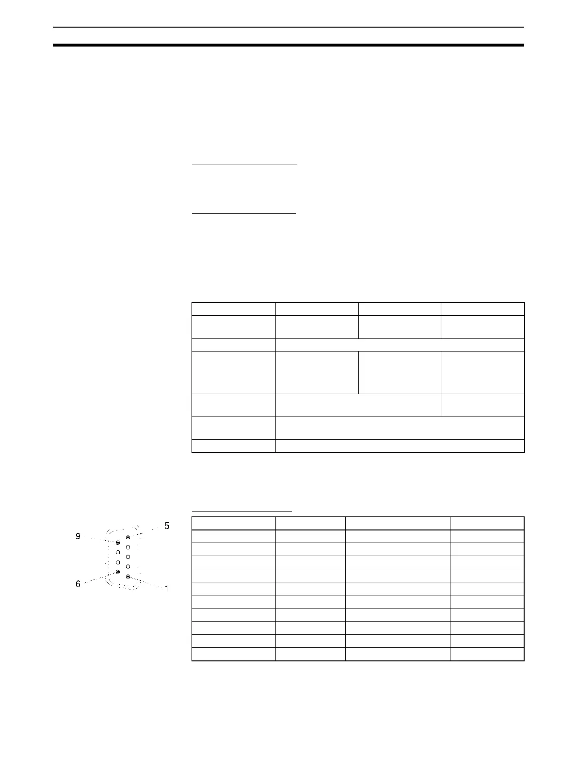
Connector Pin Layout
Note 1. When 2-wire connections are used, use Pins 1 and 2, or Pins 6 and 8.
Protocol Host Link Protocol macro 1:N NT Links
Communications
method
Full-duplex Full-duplex or half-
duplex
Half-duplex
Synchronization Start-stop synchronous (asynchronous)
Baud rate 1,200/2,400/4,800/
9,600/19,200/
38,400/57,600/
115,200 bps
1,200/2,400/4,800/
9,600/19,200/
38,400 bps
Standard NT link or
high-speed NT link
(See note.)
Connections 1:N (N: 32 Units max.) 1:N (N: 8 Units
max.)
Transmission dis-
tance
500 m max. (The total combined cable length is 500 m max. T-
branch lines must be a maximum of 10 m long.)
Interface Complies with EIA RS-485
Pin No. Abbreviation Signal name I/O
1 (see note 1) SDA Send data - Output
2 (see note 1) SDB Send data + Output
3 NC Not used ---
4 NC Not used ---
5 NC Not used ---
6 (see note 1) RDA Receive data - Input
7 NC Not used ---
8 (see note 1) RDB Receive data + Input
9 NC Not used ---
Shell (see note 2) FG Shield ---
 Loading...


