65
Component Names and Functions Section 2-1
2. The shell is connected to the ground terminal (GR) of the Power Supply
Unit inside of the Serial Communications Board. Therefore, the cable
shield can be grounded by grounding the GR of the Power Supply Unit.
3. With SDA/B or RDA/B, the signal polarity may be reversed by the remote
device. Be sure to check the polarity before wiring.
Applicable Connectors
Plug: XM2A-0901 (OMRON) or equivalent
Hood: XM2S-0911-E (OMRON) or equivalent
One plug and one hood are provided for each port.
Recommended Cables
CO-HC-ESV-3P × 7/0.2 (manufactured by Hirakawa Hewtech Corp.)
Cable length: 500 m max. (The total combined cable length is 500 m max. T-
branch lines must be a maximum of 10 m long.)
Terminating Resistance
Switch: TERM
The terminating resistance switch is provided on the CS1W-SCB41-V1 only.
When an RS-422/485 port is used, set the switch to ON if the Serial Commu-
nications Board is on the end of the transmission line. Refer to Section 3
Installation and Wiring for the ON/OFF settings.
Note The status of terminating resistance setting can be monitored in the words
allocated in the CIO Area. For details, refer to 2-3 I/O Memory Allocations.
2-Wire or 4-Wire Switch:
WIRE
The 2-wire or 4-wire switch is provided on the CS1W-SCB41-V1 only.
When an RS-422/485 port is used, set the switch to “2” when 2-wire connec-
tions are used, and set the switch to “4” when 4-wire connections are used.
For details, refer to Section 3 Installation and Wiring.
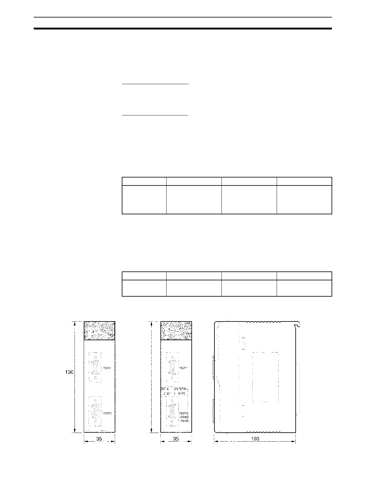
External Dimensions
Label Name Settings Factory setting
TERM Terminating
resistance switch
ON: Terminating
resistance ON
OFF: Terminating
resistance OFF
OFF: Terminating
resistance OFF
Label Name Settings Factory setting
WIRE 2-wire or 4-wire
switch
2: 2-wire
4: 4-wire
2: 2-wire
CS1W-SCB21-V1
CS1W-SCB41-V1
Mounted in the CPU Unit
SCB21-V1
SCB41-V1
130
 Loading...


