3-3SectionCommand Format
30
3-3-2 Command Format
The
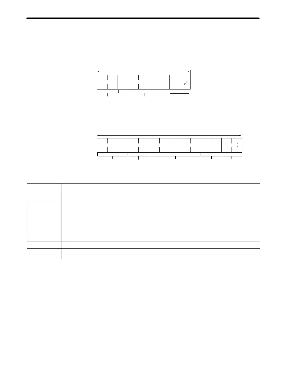
following explains the format of commands sent
from the host computer to
the ID Controller.
XXXX X
∗
.......
For 1 to 1 Procedure
1
frame = 266 characters max.
Header Text Terminator
@XXXXXX XXX
.......
∗
Header Text FCS Terminator
Controller No.
(Unit No.)
For 1 to N Procedure
1
frame = 271 characters max.
Name Contents
Header This contains the 2-character abbreviation for the command function (see
Command Response Table,
page
29
). If it is a response, the same abbreviation as that of the command sent is entered here.
Text This contains the command response.
• ASCII/Hexadecimal Code Specification
• Destination R/W Head No. Specification
• Head Address
• Write Data/Read No.
Terminator This indicates end of command response.
Controller no. Only used for 1 to N procedure, a Controller numbers 00 to 15 is added after @ mark.
FCS (see note
1)
Only used for 1 to N procedure, horizontal parity check is used.
Note 1. See
3-3-3 FCS Computation Procedure (V600-CA2A-V
j
Only)
for details
on the FCS (frame check sequence).
2. The
V600-CA1A-V
j
with an RS-232C interface can be used for the
1 to 1
and 1 to N (N = 1 only) procedure. The V600-CA2A-Vj with an RS-422
interface can be used for the 1 to 1 and 1 to N (N = 1 to 16) procedure.
3. A
controller number must be designated decimally within a range
between
@00 and @15.
3-3-3 FCS Computation Procedure (V600-CA2A-Vj Only)
FCS
operates by converting
the 8-bit data representing the exclusive OR of the
codes
for the characters from the head of the frame (@ mark) to the final charac
-
ter of text into two characters of ASCII code.

 Loading...


