5-4SectionDIP Switch Settings
83
5-4 DIP Switch Settings
Remove
the Monitor Unit connector cover on the top of the ID Controller to
make
the hardware settings for the communications interface. Check the host com-
puter
communications
specifications carefully and be sure to make the settings
correctly.
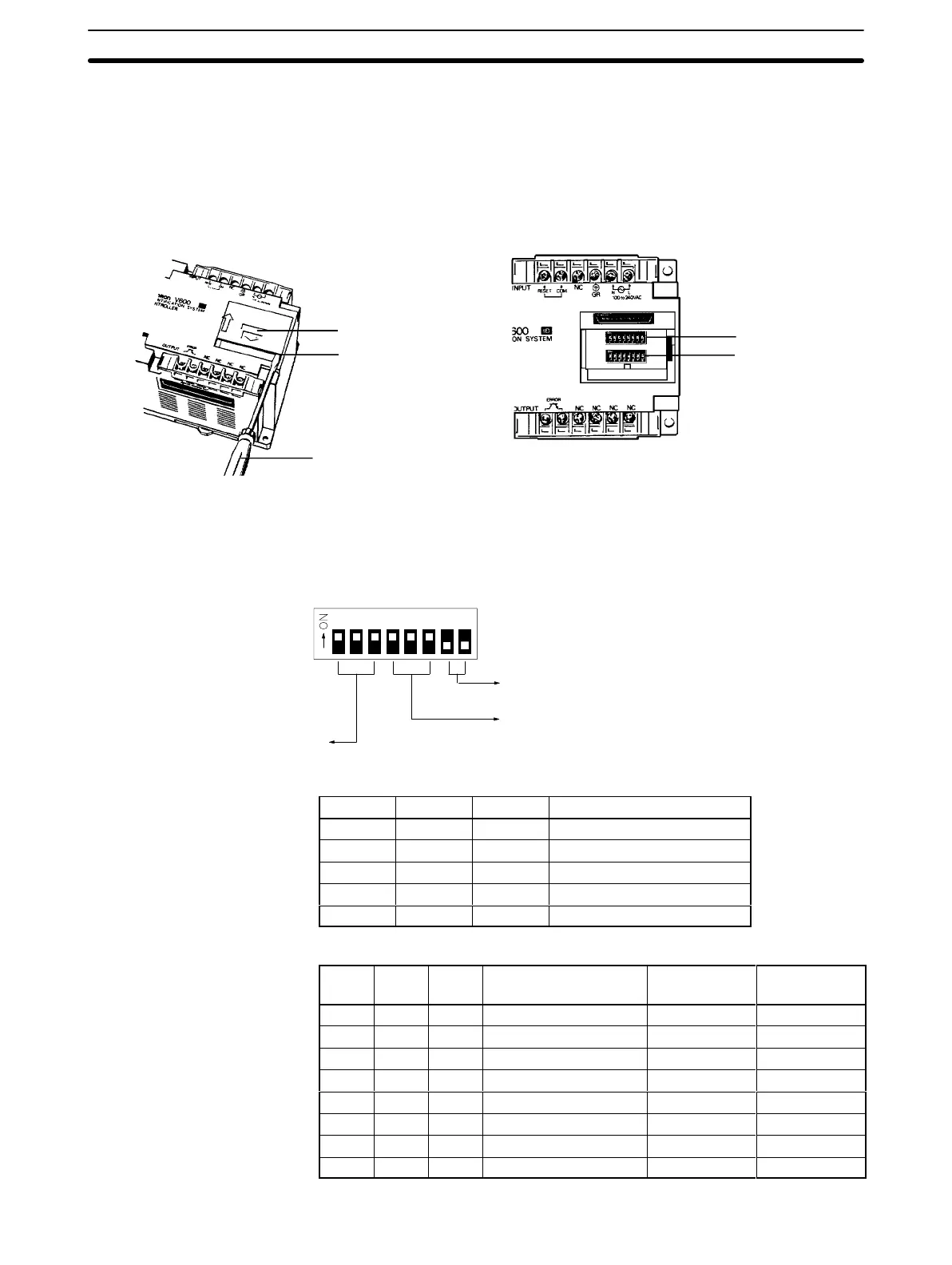
5-4-1 Removing Connector Cover
Connector cover
Notch
Slotted-head screwdriver
DIP switch 1
DIP switch 2
Slide the connector cover upwards, and insert a slotted-head screwdriver into
the notch at the right end of the cover to remove it.
5-4-2 DIP Switch Settings
1 3456782
Note: AII
pins are set to OFF before the ID Con
-
troller is shipped from the factory
.
These two pins must be set to OFF
.
Communications format
T
ransmission speed setting
DIP switch 1
MODE 1
Transmission Speed Setting
Pin
1
Pin 2 Pin 3 Transmission speed (BPS)
0 1 1 1,200
1 0 0 2,400
1 0 1 4,800
1 1 0 9,600
1 1 1 19,200
Communications Format
Pin
4
Pin 5 Pin 6 No. of bits for data
length (see note 1)
No. of stop
bits
Parity setting
(see note 2)
0 0 0 7 2 E
0 0 1 7 2 O
0 1 0 7 1 E
0 1 1 7 1 O
1 0 0 8 2 N
1 0 1 8 1 N
1 1 0 8 1 E
1 1 1 8 1 O

 Loading...


