5-6SectionRS-422 Interface
88
Note 1. GR is grounded to the connector hood and connected to the ID Controller
ground
via the connector hood, and consequently connection to pin 1 is not
necessary.
2. Short pins 4 (RS) and 5 (CS) using a crossover line.
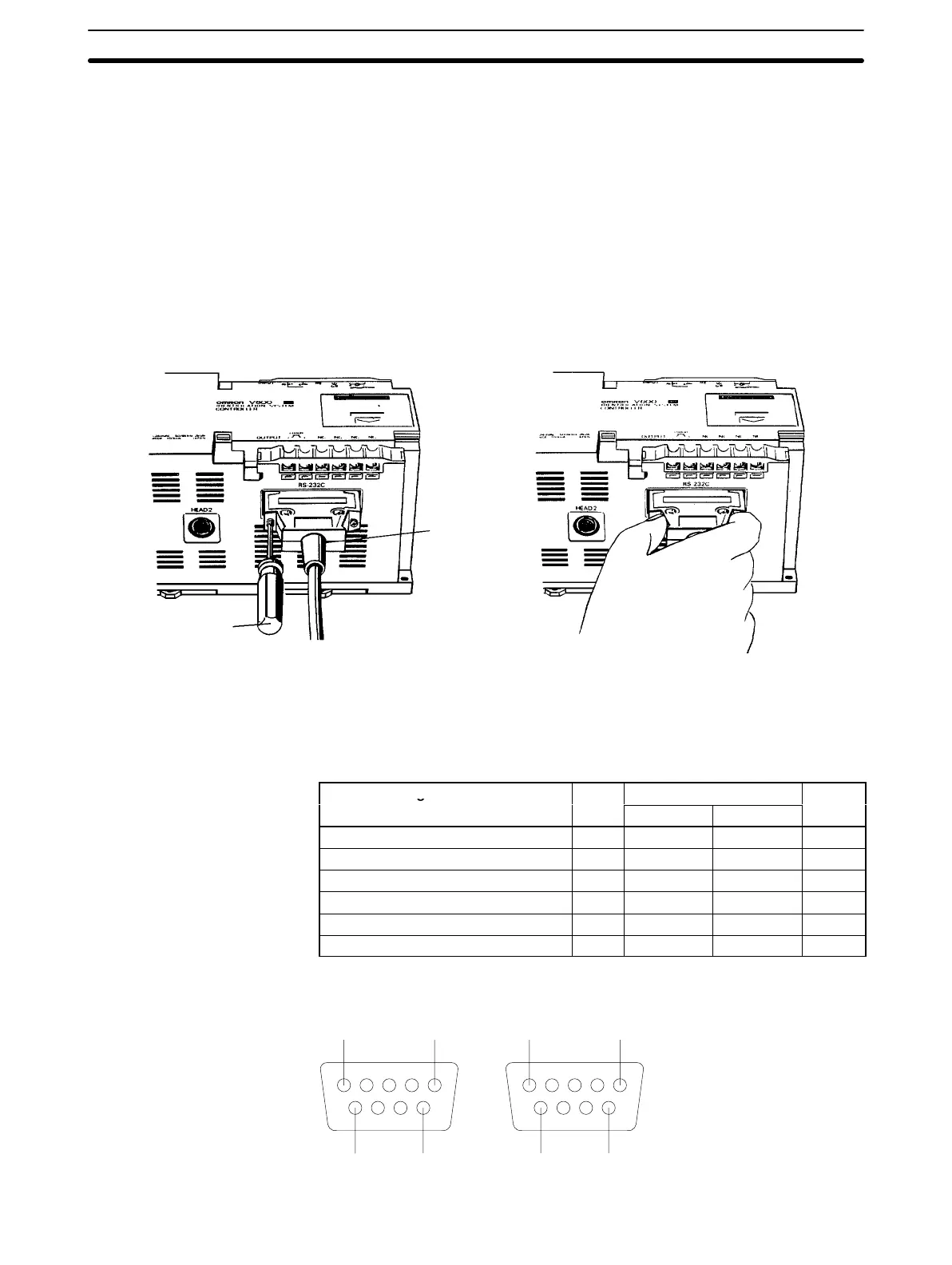
5-5-3 Insertion and Removal of Connector
It
is extremely important to hand-hold the connector to attach and insert it prop
-
erly. After inserting the connector, take a Phillips head screwdriver and fully
tighten
the two lock screws. T
o remove
the connector
, completely unscrew the
two lock screws, and take out the protruding section of the connector hood by
hand
and pull it straight out. If it is dif
ficult to remove, hold the ID Controller down
with one hand and pull carefully on the connector with the other.
Lock screw
(T
wo, M2.6)
Phillips head
screwdriver
(for M2.6)
5-6 RS-422 Interface
The following settings must be made when the V600-CA2A-Vj is used.
Signal name Abbr.
Signal direction
Pin no.
Input Output
Safety ground or earth ground FG --- --- 7
Signal ground or common return line SG --- --- 3
Send data 1 SDA --- Required 9
Receive data 2 SDB --- Required 5
Receive data 1 RDA Required --- 6
Receive data 2 RDB Required --- 1
51
96
51
96
Pin Arrangement (Soldering-side View)

 Loading...


