5-5SectionRS-232C Interface
87
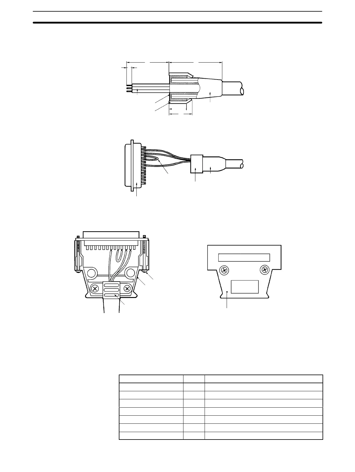
5-5-2 Connector Assembly
1, 2, 3...
1. Perform cable terminal processing.
Conductor
lines
Shield braid
Shield tape
Cable bushing
35
40
5
12
10±1
2. Solder conductor lines and plug pins.
Cable
bushing
Plug
Crossover
Aluminum tape
3. Set the hood housing A2 onto the plug, and fix the aluminum tape section
with a clamp.
Lock screw (2-M2.6)
Housing A2
Cable clamp
Housing B2
4. Tighten
the two connector holding screws, and then cover this with housing
B2 to complete the connector assembly.
Note 1. First pass the cable through the cable bushing.
2. Unwind
the shielded braid and turn back over the cable bushing. Unwind 10
mm of the shielded braid and turn back over the cable bushing.
3. Wrap the lines with sealing tape.
Pin no. Abbr. Name
1 (see note 1) GR Ground
7 SG Signal ground
2 SD Send data
3 RD Receive data
4 (note 2) RS Request send
5 (see note 2) CS Can send
20 ER Data terminal ready

 Loading...


