5-3SectionWiring Procedures
80
5-3 Wiring Procedures
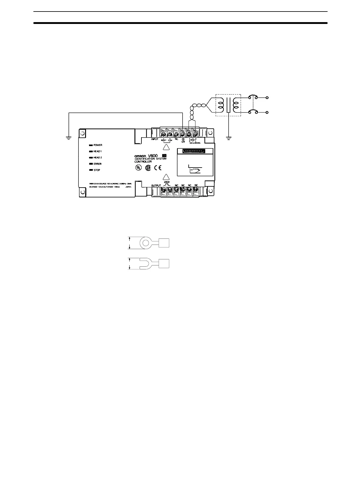
5-3-1 Power Supply and Ground Line Wiring
The ID Controller conforms to IEC1010-1, EN61010-1, UL3101, and
CSA1010-1. Therefore, field wiring is readily available.
Class
3
ground
Breaker
Insulated transformer
AC power supply:
100 to 240 V
AC,
50/60 Hz
!
!
• The screws used on the power supply and the protective conductor terminal
are
M3.5 self-tapping screws. If a crimp-on terminal is to be used, select one
from those shown below. Ensure that the binding torque is about 8 kg • cm.
7.0
max.
7.0 max.
(for M3.5 screws)
• Ensure that the line voltage is in the range of 100 to 240 VAC. It is also
extremely
important to ensure that the permissible voltage variation range of
85 to 264 VAC is not exceeded.
• The
ID Controller has internal components to deal with noise
from the power
line,
and supplying power
via a 1:1 insulated transformer drastically attenuates
ground noise.
• The
ID Controller power consumption is less than 35 V
A using the maximum
configuration,
but when setting up the power supply
, note that there is a surge
current
of approximately 15 A (at 100 V
AC)
when power is applied to the sys
-
tem.
• Use
a power cable with at least a 2-mm
2
cross-section with no voltage drop. It
is recommended that the power wires be twisted for use.
• To prevent electric shocks and improve noise resistance, independently
ground the ID Controller at a resistance of less than 100 Ω.
• Do not use the open terminal (NC terminal).
5-3-2 Input/Output Line Wiring Precautions
Reset Signal Input
• Take
suf
ficient care to ensure that the input voltage does not exceed the maxi
-
mum applied voltage (26.4 V). Exceeding the permissible voltage level will
damage the equipment.

 Loading...


