5-3SectionWiring Procedures
81
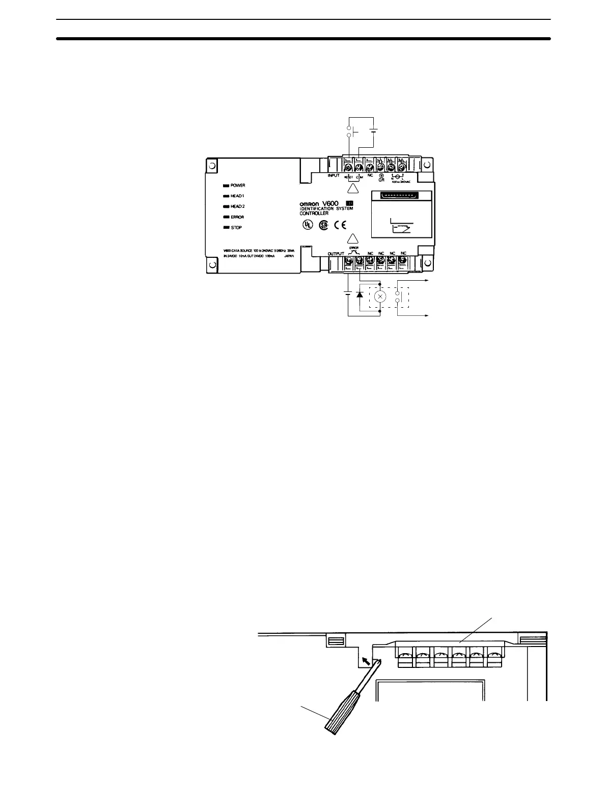
• Lay
the input line
away from high-voltage equipment or power lines to improve
noise resistance of the lines.
Reset
input
24VDC
T
o error output
24VDC
+
+
!
!
Error Signal Output Wiring
• The
output section maximum switching capacity is 100 mA at 24 VDC (+10%,
–15%).
Applying voltages or loads that exceed the switching capacity will
dam
-
age the equipment.
• It
is recommended that auxiliary relays (100 mA max. at 24 VDC) be used in
the output circuit.
Note The
reset signal input terminal and error signal output terminal will be supplied
from an SELV source in accordance with IEC1010-1 Annex I-I.
5-3-3 Removing Terminal Cover
The terminal cover must be removed with a slotted-head screwdriver in the
direction (A).
Terminal cover
Slotted-head screwdriver
(A)

 Loading...


