5-5SectionRS-232C Interface
86
5-5 RS-232C Interface
The following settings must be made when the V600-CA1A-Vj is used.
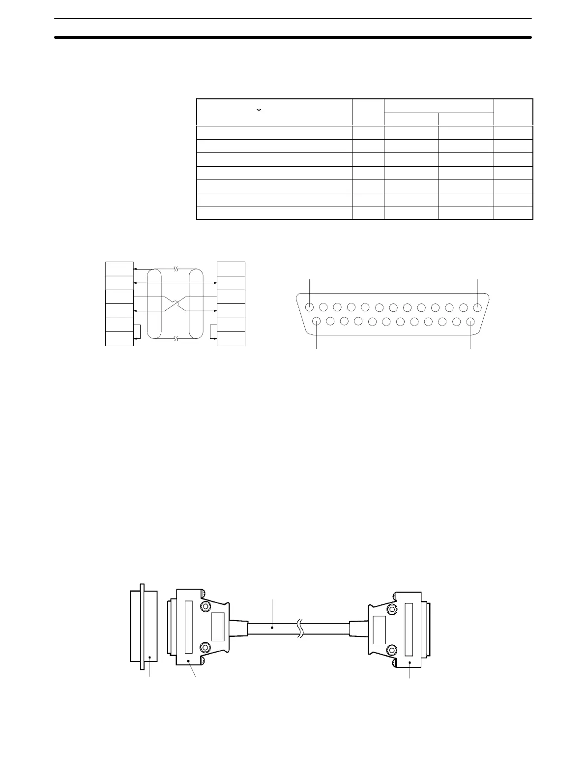
Signal name Abbr.
Signal direction
Pin no.
Input Output
Safety ground or earth ground GR --- --- 1
Signal ground or common return line SG --- --- 7
Send data SD --- Required 2
Receive data RD Required --- 3
Request send RS --- Required 4
Can send CS Required --- 5
Data terminal ready ER --- Required (20)
GR
SG
SD
RD
RS
CS
FG
SG
SD
RD
RS
CS
ID
Controller
(Shielded wire)
Host computer
13 1
25 14
Pin Arrangement (Soldering-side View)
Note 1. Ground
the shielded wire at only one end, either the ID Controller or the host
computer
to prevent mis-operation. The diagram at the upper-left is a wiring
example with the shielded wire grounded at the ID Controller.
2. Make
an internal short between pins 4 (RS) and 5 (CS) before using the con
-
nector.
5-5-1 Assembling and Connecting Communications Connector
Use
the connector provided as an ID Controller accessory as the communica
-
tions
connector
.
The user must provide the connecting cable and the host com
-
puter
connector
. The OMRON
ID Controller Connector is protected from electro
-
magnetic interference (EMI).
XM2A-2501
Plug*
(ID Controller accessory )
(Made by OMRON)
XM2S-251
1 Hood*
(ID Controller accessory )
(Made by OMRON)
Connecting cable
At host computer
Recommended cable:
CO-DS-IREVV
-SX10 pins,0.18mm
2
FD
(Hitachi Densen)
RS-232C recommended connector:
XM2A-2501,
XM2S-2511
(Made by OMRON)
At ID Controller

 Loading...


