5-4SectionDIP Switch Settings
85
Use
the connector provided
as an accessory as the communications connector
.
The
user must provide the connecting cable. If a connector other than the acces
-
sory
connector is to be used, see the list of applicable connector model numbers
at the end of this manual.
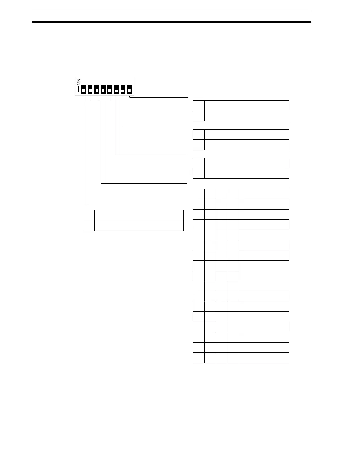
Pin 1 Slave communication mode setting
1
0
13456782
Pin 8 (V600-CA2A-Vj only)
Pin 7 (V600-CA2A-Vj only)
ID
Controller unit number settings
1
0
1
0
Pin
6
Termination resistor connected (ID
Controller transmission side)
T
ermination resistor not connected
T
ermination resistor connected (ID
Controller transmission side)
T
ermination resistor not connected
1 to N procedure
1 to 1 procedure
0000
Unit 0
0001
Unit 1
0010
Unit 2
0011
Unit 3
0100
Unit 4
0101
Unit 5
0110
Unit 6
0111
Unit 7
1000
Unit 8
1001
Unit 9
1010
Unit 10
1011
Unit 1
1
1100
Unit 12
1101
Unit 13
1110
Unit 14
1111
Unit 15
Unit No.
Pin 5Pin 4Pin 3Pin 2
Ensure that there is no duplication of unit number
.
Communication speed priority setting
Communication distance priority setting
1
0
DIP switch 2
MODE 2
Pin 1 Setting Pin
1 setting is ef
fective only when the user has access to a EEPROM DC (with
no
battery). Pin 1 setting has nothing to
do with a SRAM DC (with a built-in bat
-
tery). Refer to
R/W Head and Data Carrier Operation Manuals
for details.
Pin 6 Setting When selecting the 1 to N procedure on the V600-CA1A-Vj and RS-232C
Interface, N must be 1. In this case, it is possible to add a check code FCS.

 Loading...


