4-6SectionReading Error Information (ERR)
72
5. Press Key 4 to select auto write, and then TAW is shown on the display.
Head 1 indicator lights now.
6. When the DC enters the operation range, the specified data is sent to the
memory
area defined by the start and end addresses, and Head 1 indicator
flashes while processing occurs.
Note When
only T
A
W is shown on the display
, and no data is displayed, this
indicates
the DC waiting condition. When an error code is displayed,
use the horizontal cursor keys to display the error message.
4-6 Reading Error Information (ERR)
All communications, system, and other errors occurring in the RUN Mode are
stored
in the ID Controller RAM.
The latest error statistics (30 items maximum)
can be read or cleared using the Monitor Unit.
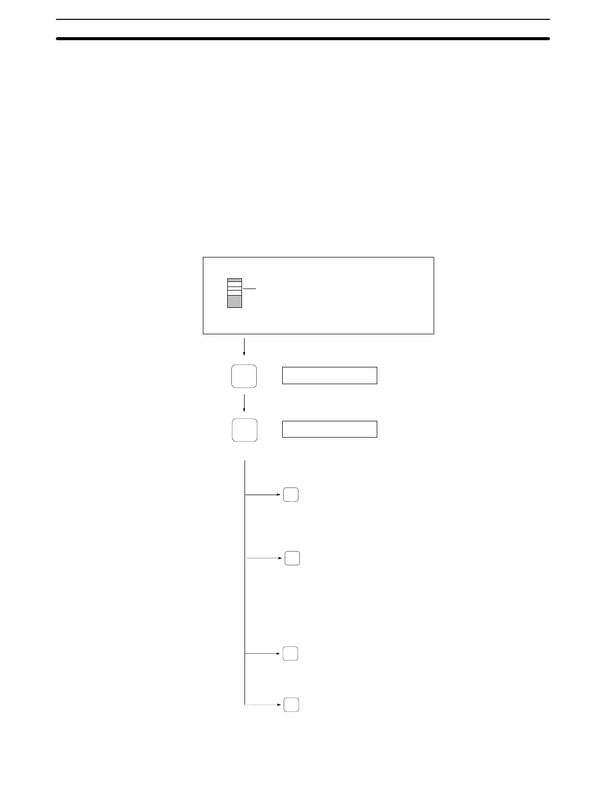
Error Logging Menu Selection
RESET
a00d00
(1)
ERROR14
(2)
(Error
mode selection menu)
ERR
MONITOR Mode switchMONITOR
1
2
3
4
1, 2, 3...
1. The
ERR Key
is not ef
fective when MONIT
OR is shown on the display
, so
press the RESET Key to display the address and data.

 Loading...


