5-6SectionRS-422 Interface
89
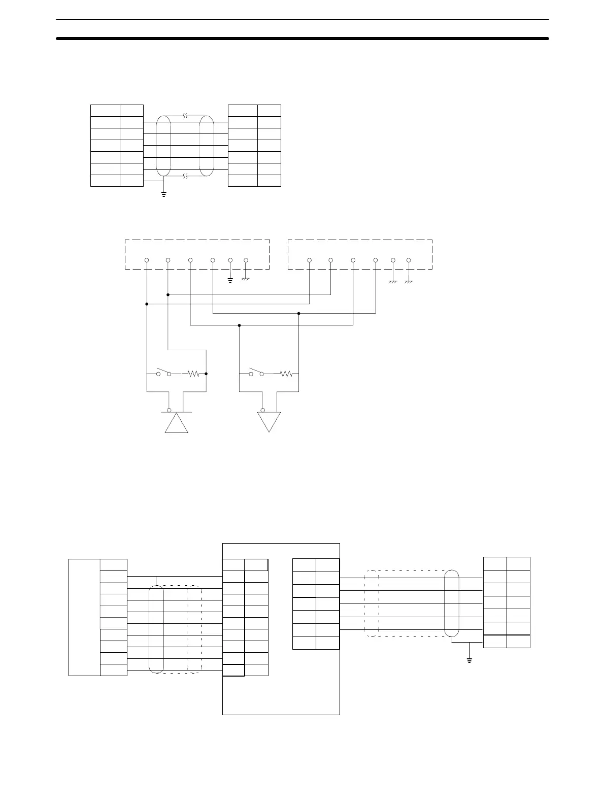
5-6-1 Connections Between ID Controllers for 1 to N Connection
PinNo.
9
5
6
1
3
7
FG
SDA
SDB
RDA
RDB
SG
Abbr.
ID
Controller
PinNo.
9
5
6
1
3
7
FG
SDA
SDB
ROA
RDB
SG
Abbr.
ID Controller
Note:
Ground either end of the shielded wire to prevent the
ID Controllers from malfunctioning. Do not ground both
ends of the shielded wire, otherwise the ID Controllers
may not operate properly
. When using an
EMI-preventive connector (provided with the ID
Controller), connect the ground line to the connector
hood and not to the connector pin.
SDA SDB RDA RDB SG FG SDA SDB RDA RDB SG FG
Reception side
termination resistor
Transmission side
termination resistor
Note: The
termination resistance is 220
Ω.
T
urn on the termination resistors of the
end Units. T
urn of
f the termination
resister of any other Unit, otherwise
normal transmission will not be possible.
5-6-2 Connection to Host Computer
Host Computer with Built-in RS-232C Interface
Pin No.
FG
Abbr.
SDA
SDB
RDA
RDB
SG
Host
computer
Shielded cable (Note 1)
Notes: 1.
Connection example of shielded cable grounded at host computer
.
2.
Connection example of shielded cable grounded at ID Controller
.
Link adapter 3G2A9-AL004(-P)
RS-422
Shielded cable
ID Controller
(Note 2)
1
2
3
4
5
6
7
8
20
Abbr.
FG
SD
RD
RS
CS
DR
SG
CD
ER
RS-232C
Interface
Pin No.
1
2
3
4
5
6
7
8
20
9
5
6
1
3
7
Pin No.
RS-232C
FG
Abbr.
SDA
SDB
RDA
RDB
SG
9
5
6
1
3
7
Pin No.

 Loading...


