5-6SectionRS-422 Interface
90
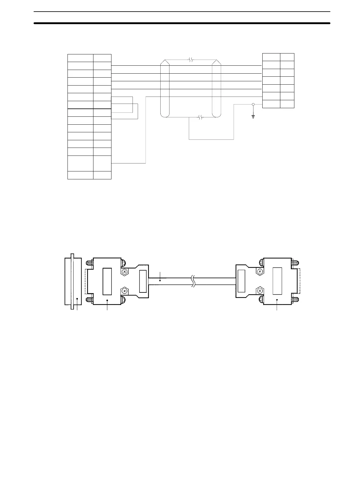
Host Computer with Built-in RS-422 Interface
FG
Abbr.
RDB
RDA
SDB
SDA
SG
Pin No.
A4
B4
A3
B3
A6
B6
Abbr.
SD+
SD–
RD+
RD–
RS+
RS–
A5
B5
B7
A7
B9
A9
CS+
CS–
ER+
ER–
CD+
CD–
SG
A12,B12 FG
PinNo.
1
6
5
9
3
7
A10,B10
A11,B11
Shielded
cable
ID Controller
Notes: 1.
Ground the shielded cable at one end
or the other
.
2. T
urn on only one of the termination
resistors either at the ID Controller
cable terminal or at the Host Link Unit.
Host computer
5-6-3 Assembling and Connecting Communications Connector
Use
the connector provided as an accessory with the ID Controller for the com
-
munications connector. The user must provide the connecting cable and the
host computer connector. The OMRON ID Controller connector is protected
from electromagnetic interference (EMI).
At
ID Controller
Connecting cable
XM2A-0901 Plug*
(made by OMRON)
XM2S-091
1 Head*
(made by OMRON)
*T
wo sets of EMI-protected connectors are pro
-
vided as an accessory with the ID Controller
At host computer
RS-422 recommended connector:
XM2A-0901 (connector)
XM2S-0911 (connector cover)
(made by OMRON)
5-6-4 Connector Assembly Procedure
Perform cable end processing. Refer to the drawings below for the lengths of
each type of cable end processing.
End of Shielded Cable Connected to FG
1, 2, 3...
1. Cut cable at required length.
2. Use
a razor blade to remove the sheath. A
void damaging
the shielded lines
(braid) when cutting off the sheath.
3. Cut shielded cable using scissors.
4. Bare each line using a stripper.
5. Bend the shielded lines back.

 Loading...


