5-6SectionRS-422 Interface
91
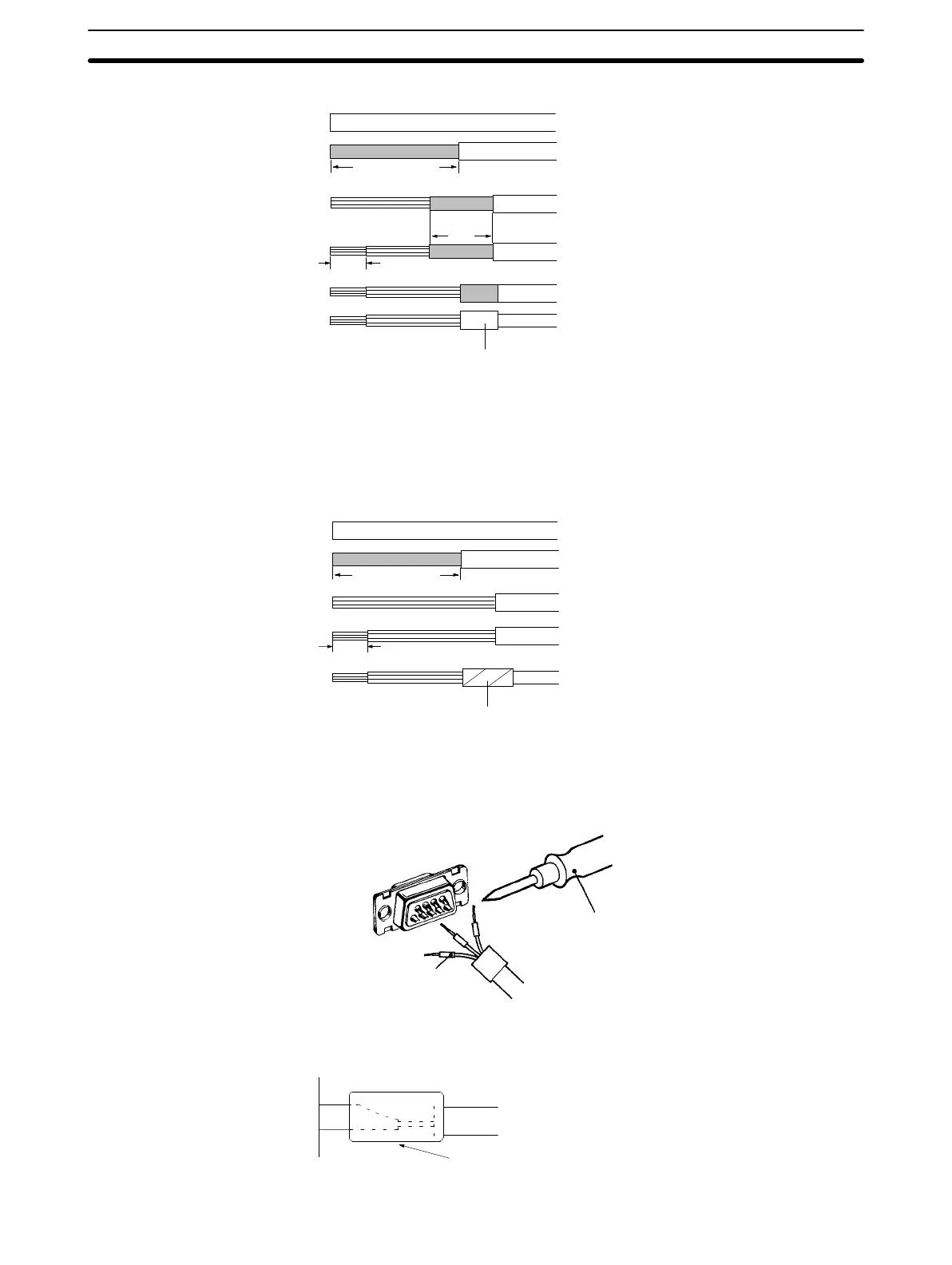
6. Cover the bent back lines with aluminum foil tape.
Aluminum
foil tape
10
25(RS-422)
40(RS-232C)
5
End of Shielded Cable Unconnected to FG
1, 2, 3...
1. Cut cable at required length.
2. Use a razor blade to remove the sheath.
3. Cut shielded cable using scissors.
4. Bare each line using a stripper.
5. Cover the cut section of the shielded cable with vinyl tape.
Vinyl
tape
25(RS-422)
40(RS-232C)
5
Soldering
1, 2, 3...
1. Place a thermal contraction tube on each line.
2. Perform preliminary soldering on each line and connector terminal.
3. Perform soldering on each line.
Soldering
iron
Thermal contraction tube
(Internal diameter
1.5mm,
l=10)
4. Pull
back
thermal contraction tubes to soldered sections, then use a jetter to
apply heat to contract them.
Thermal
connection tube

 Loading...


