EasyManuals Logo

Omron V600 Series Operation Manual

Omron V600 Series
115 pages
To Next Page IconTo Next Page
To Previous Page IconTo Previous Page
Page #95 background imageLoading...
Page #95 background image
5-6SectionRS-422 Interface
92
Hood Assembly Assemble the connector hood.
End
connected
to FG
Aluminum
foil tape
End not connected
to FG
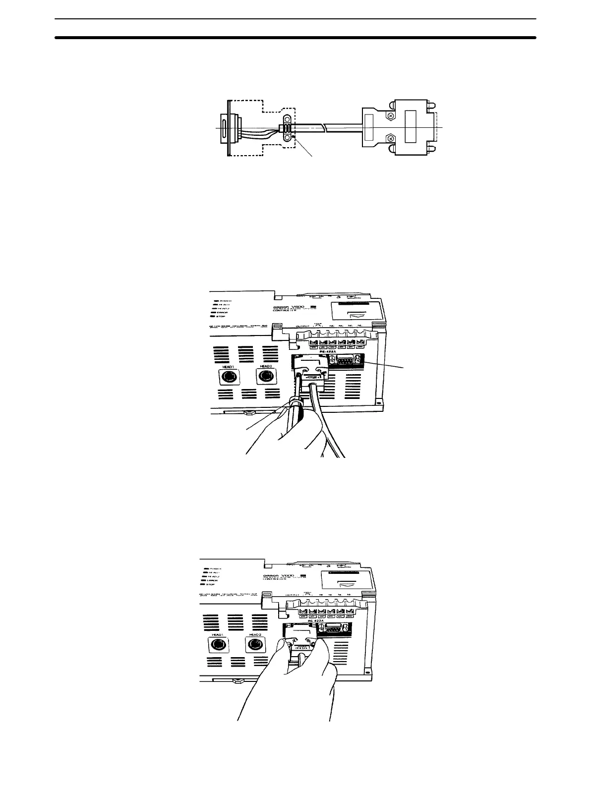
5-6-5 Insertion and Removal of Connector
It
is extremely important to hand-hold the connector to attach and insert it prop
-
erly. After inserting the connector, take a Phillips head screwdriver and fully
tighten the two lock screws.
Lock screws
(T
wo, M2.6)
Phillips head
screwdriver
(for M2.6)
To
remove the connector
, completely unscrew the two
lock screws, and take out
the protruding section of the connector hood by hand and pull it straight out.
If
it is dif
ficult to remove, hold the ID Controller down with one hand and pull care
-
fully on the connector with the other.

Other manuals for Omron V600 Series

Questions and Answers:

Question and Answer IconNeed help?

Do you have a question about the Omron V600 Series and is the answer not in the manual?

Omron V600 Series Specifications

General IconGeneral
Operating Frequency13.56 MHz
Supported StandardsISO 15693, ISO 18000-3
Read RangeUp to 70 mm (depending on tag and environment)
Power Supply24 VDC ±10%
Operating Temperature-10 to 55°C (with no icing or condensation)
Humidity35% to 85% (non-condensing)
Communication InterfaceRS-232C

Related product manuals