42
SECTION 2
Connection and Wiring
RFID System
User’s Manual
SECTION 2
Installation, Connections, and Wiring
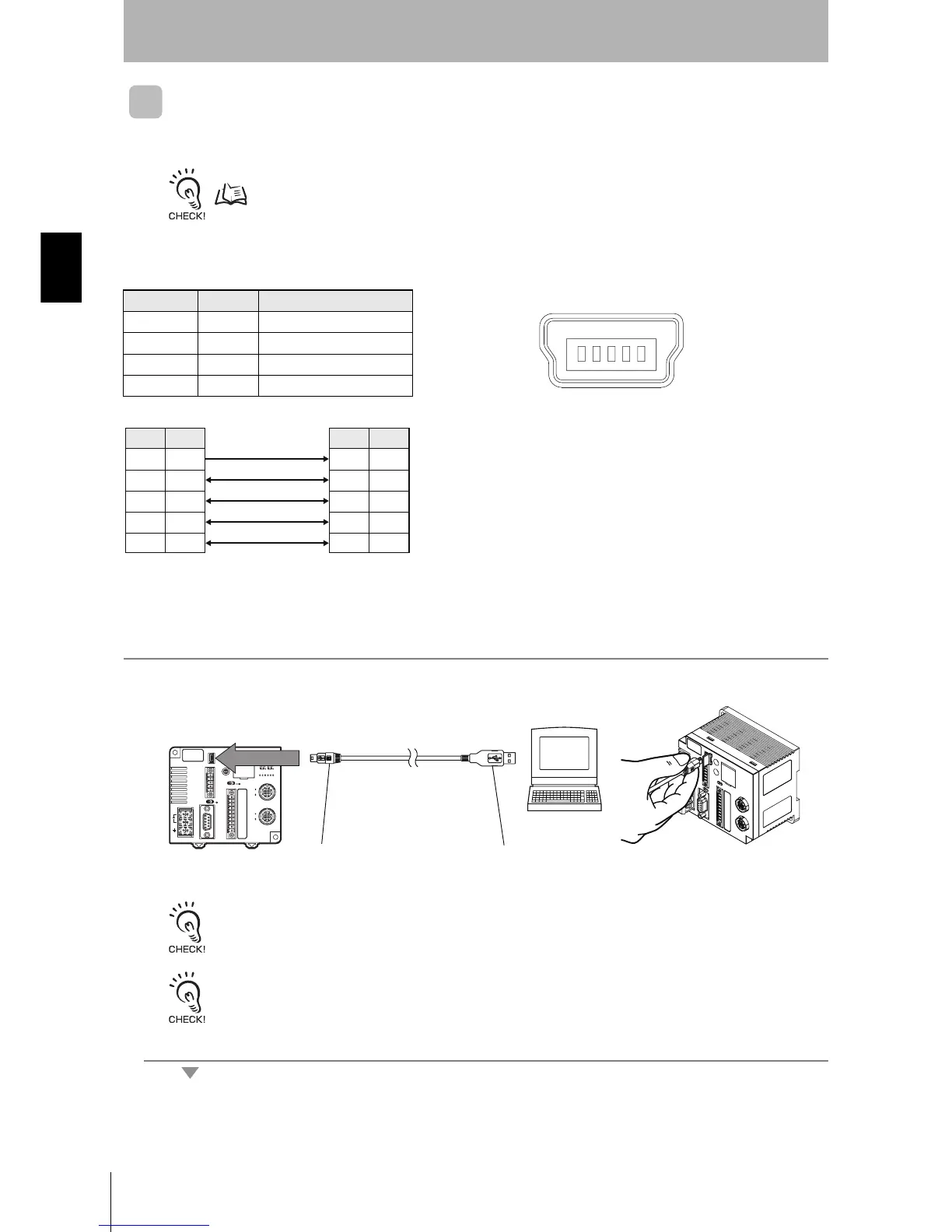
USB Port
The USB port is connected to a USB cable (Series A-Mini USB series B connectors).
The USB port is not a control port. Always use the RS-232C port or RS-422/RS-485 port for system configuration.
p. 19
Pin Arrangement
Connecting and Disconnecting Connectors
1. Connect the Mini USB series B end of the connector to the ID Con-
troller.
A cap is attached to the connectors at shipment. Leave this cap on if USB is not being used to prevent dust or foreign
matter from entering the connectors and to prevent static electricity.
Removing Connectors
Hold the base of the connector and pull straight out. If the connector is difficult to remove, press the ID Controller while
pulling on the connector.
Pin No. Name Description
1 VBUS Power supply
2D
− USB data (−)
3 D+ USB data (+)
5 GND Ground
Terminal No.
123 45
• Controller Terminal Arrangement
Pin No. Pin No.
Symbol
Symbol
11
2
2
3
3
54
-
-
VBUS
VBUS
D −
D −
D + D +
GND
GND
GR
GR
Series B end
Series A end