16
Wiring Chapter 2-2
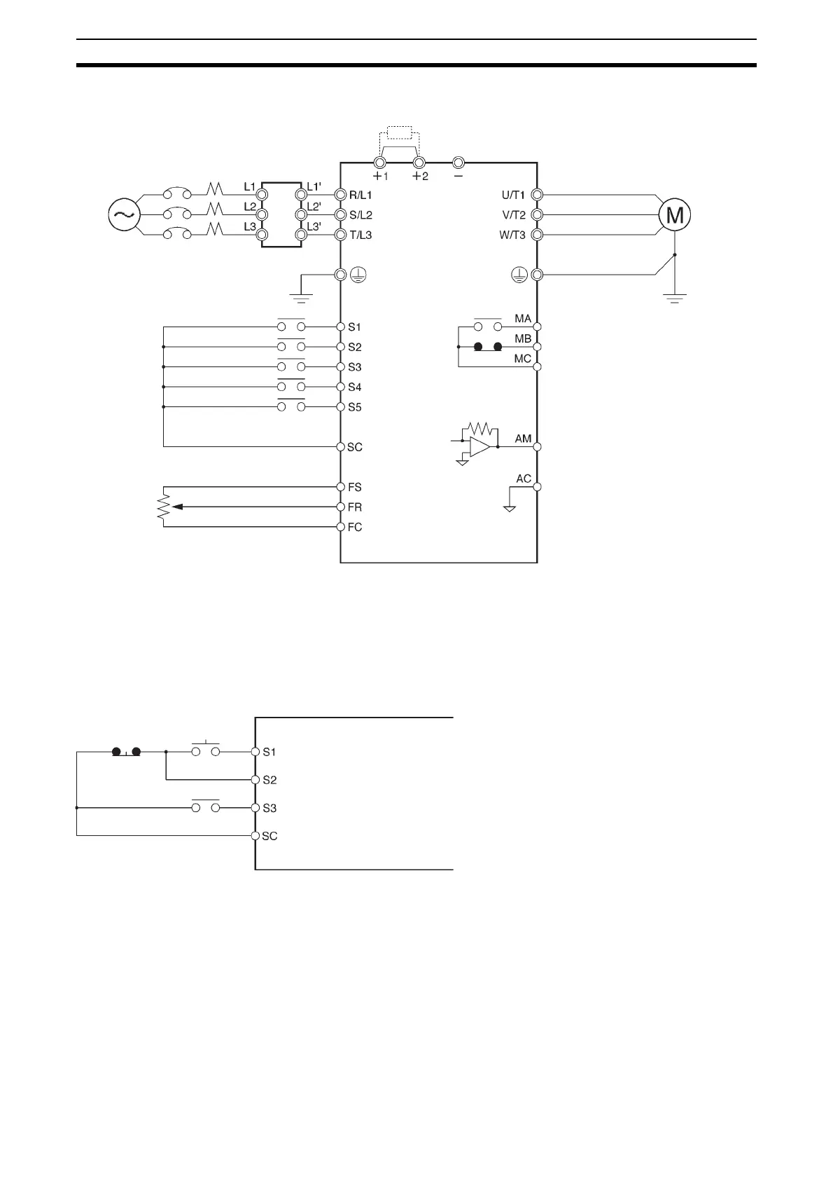
2-2-3 Standard Connections
Note 1. Connect single-phase 200 V AC to terminals R/L1 and S/L2 of the CIMR-
J7AZB_.
2. The braking resistor cannot be connected because no braking transistor is
incorporated.
Example of 3-wire Sequence Connections
Note Set parameter n37 for 3-wire sequence input.
Noise Filter
DC reactor
(optional)
3-phase 200 V AC
Single-phase 200 V AC
(see note 1)
3-phase 400 V AC
Multi-function contact output
NO
NC
Common
Analog monitor output
Analog monitor output common
Forward/Stop
Multi-function input 1 (S2)
Multi-function input 2 (S3)
Multi-function input 3 (S4)
Multi-function input 4 (S5)
Sequence input common
Frequency reference power
supply 20 mA at +12 V
Frequency reference input
Frequency reference common
(2kΩ, 1/4 W min.)
FREQ
adjuster
Stop
switch
(NC)
RUN
switch
(NO)
Direction switch
RUN input (Operates with the stop switch and RUN switch closed.)
Stop input (Stops with the stop switch opened.)
Forward/Stop reference (Forward with the direction switch opened
and reverse with the direction switch closed.)
Sequence input common