Section 1 FEATURES
Section 1
Part Names and Functions
19
ZFV
User’s Manual
(5) Mode selector switch
This switch selects the operating mode.
MENU...Select this mode when setting measurement conditions.
ADJ...Select this mode when adjusting the judgment threshold value.
RUN...Select this mode when performing measurement.
Output is performed only when the RUN mode is currently selected.
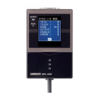
(6) LCD monitor
The LCD monitor displays setup menus and images captured from the Sensor Head.
(7) Sensor Head connector
This connector connects the Sensor Head.
(8) Coupler
This connector is used to connect two or more Amplifier Units. It is located on both
sides of the Amplifier Unit.
(9) I/O Cable
The I/O cable connects the Amplifier Unit to the power supply and external devices,
such as timing sensors or programmable controllers.

 Loading...