B-71ZX-E Series
ZX-E Series
Mutual Interference
Note: The figures in parentheses apply when the mutual interfer-
ence prevention function is used.
Compatibility
Sensors and Amplifier Units are mutually compatible. Sensors
can be added or replaced individually.
Influence of High-frequency Electromagnetic Fields
Using the product in the vicinity of devices that generate high-
frequency electromagnetic fields, such as ultrasonic cleaning
equipment, high-frequency generators, transceivers, mobile
phones, and inverters, may result in malfunction.
Influence of Metallic Objects
When installing the product, separate it from metallic objects
by the distances shown below.
Influence of Metallic Objects
Wiring
Wiring Check
After wiring is completed, before turning ON the power, con-
firm that the power supply is connected correctly, that there
are no faulty connections, such as load short-circuits, and that
the load current is correct. Incorrect wiring may result in failure.
Cable Extension
Do not extend the cable for the Sensor and the Amplifier Unit
to a length exceeding 10 m. Use a ZX-XC@A Extension Cable
(sold separately) to extend the Sensor’s cable. Extend the
Amplifier Unit’s cable using a shielded cable of the same type.
Power Supply
When using a commercially available switching regulator, ground
the FG (frame ground) terminal.
If the power supply line is subject to surges, connect a surge ab-
sorber that meets the conditions of the operating environment.
Calculating Unit
When using a Calculating Unit, connect the linear output ground
of the corresponding Amplifier Unit.
Connectors
Do not connect or disconnect connectors while the power is ON.
Be sure hold to connectors by the cover when connecting or
disconnecting.
Mounting
Handling
When mounting the Sensor Head, do not apply excessive shock
by, for example, using a hammer. Doing so may result in damage
or a reduction in the level of water-proofing. Also, there are screw-
shaped models that require a toothed washer to allow for a toler-
ance in the tightening torque for the nut.
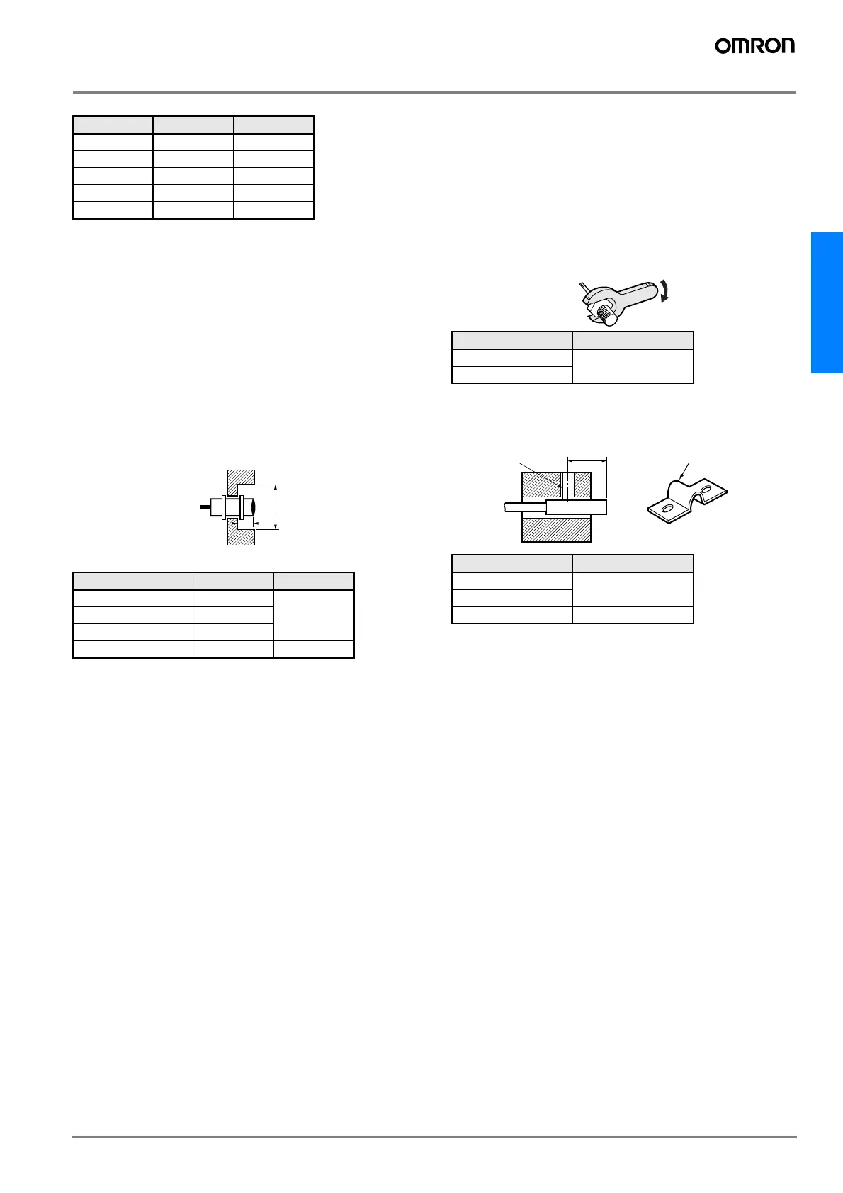
Tightening Torque
Do not apply excessive torque when tightening the nut. Use a
toothed washer if necessary.
Note: The above figure applies for use with a toothed washer.
Mounting Cylindrical Models:
Tighten set screws with a tightening torque of 0.2 N·m max.
Installation Location
Do not install the product in the following locations.
• Locations subject to temperatures outside the specified range
• Locations subject to condensation due to sudden temperature
changes
• Locations subject to humidity levels outside range 35% to 85%
• Locations subject to corrosive or flammable gases
• Locations subject to dust, salts, or metallic powder.
• Locations directly subject to vibrations and shocks
• Locations subject to direct sunlight
• Locations subject to splashes of water, oil, or chemicals
• Locations subject to strong electromagnetic or electrical fields
Maintenance and Inspection
• Be sure to turn OFF the power supply before adjusting or removing
the Sensor Head.
• Cleaning:
Do not use thinners, benzine, acetone, or kerosene for cleaning.
Model A B
ZX-EDR5T 5 mm 20 (3.1) mm
ZX-ED01T 10 mm 50 (5.4) mm
ZX-ED02T 20 mm 50 (8) mm
ZX-EM02T 20 mm 50 (10) mm
ZX-EM07MT 100 mm 150 (30) mm
Model d D
ZX-EDR5T 8 mm 9 mm
ZX-ED01T 10 mm
ZX-ED02T/EM02T 12 mm
ZX-EM07MT 55 mm 20 mm
D
d dia.
Model Tightening torque
ZX-EM02T 15 N·m
ZX-EM07MT
Model A
ZX-EDR5T 9 to 18 mm
ZX-ED01T
ZX-ED02T 11 to 22 mm
Mounting Bracket
Y92E-F5R4 (for 5.4-dia.
screws), sold separately
A
Set screw hole
 Loading...