B-66 Displacement sensors / Width-measuring Sensors
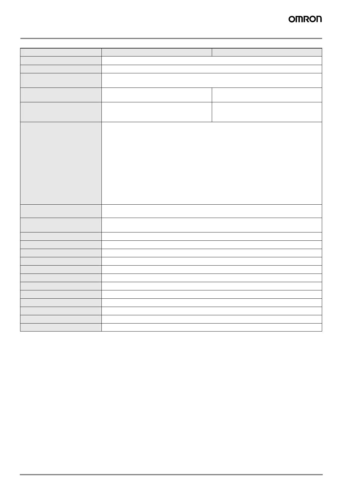
Amplifier Units
*1:The response speed of the linear output is calculated as the measurement period × (average count setting + 1) (with fixed sensitivity).
The response speed of the judgement outputs is calculated as the measurement period × (average count setting + 1) (with fixed sensitivity).
*2: The output can be switched between a current output and voltage output using a switch on the bottom of the Amplifier Unit.
*3: Setting is possible via the monitor focus function.
*4: A Calculating Unit (ZX-CAL or ZX-CAL2) is required.
Model ZX-EDA11 ZX-EDA41
Measurement period
150 µs
Possible average count settings *1
1, 2, 4, 8, 16, 32, 64, 128, 256, 512, 1,024, 2,048, or 4,096
Linear output *2
Current output: 4 to 20 mA/F.S., Max. load resistance: 300 Ω
Voltage output:±4 V (± 5 V, 1 to 5 V *3), Output impedance: 100 Ω
Judgement outputs
(3 outputs: HIGH/PASS/LOW)
NPN open-collector outputs, 30 VDC, 50 mA max.
Residual voltage: 1.2 V max.
PNP open-collector outputs, 30 VDC, 50 mA max.
Residual voltage: 2 V max.
Zero reset input, timing input, reset
input, judgement output hold input
ON: Short-circuited with 0-V terminal or 1.5 V or
less
OFF: Open (leakage current: 0.1 mA max.)
ON: Supply voltage short-circuited or supply volt-
age within 1.5 V
OFF: Open (leakage current: 0.1 mA max.)
Function
- Measurement value display - Set value/output value/resolution display
- Linearity adjustment (materials selection) - Scaling
- Display reverse - Display OFF mode - ECO mode
- Number of display digit changes - Sample hold - Peak hold
- Bottom hold, peak-to-peak hold - Self-peak hold - Self-bottom hold
- Average hold - Delay hold - Zero reset
- Initial reset - Linearity initialization - ON-delay timer
- OFF-delay timer - One-shot timer - Previous value comparison
- Non-measurement setting - Direct threshold value setting - Position teaching
- Automatic teaching - Hysteresis width setting - Timing inputs
- Reset input - Judgement output hold input - Monitor focus
- Linear output correction - (A-B) calculations *4 - (A+B) calculations *4
- K-(A+B) calculation *4 - Mutual interference prevention *4
- Sensor disconnection detection - Zero reset memory - Zero reset indicator
- Key lock
Indications
Judgement indicators: High (orange), pass (green), low (yellow), 7-segment main digital display (red),
7-segment sub-digital display (yellow), power ON (green), zero reset (green), enable (green)
Voltage influence
(including Sensor)
0.5% F.S. of linear output value at ±20% of power supply voltage
Power supply voltage
12 to 24 VDC ±10%, Ripple (p-p): 10% max.
Current consumption
140 mA max. with power supply voltage of 24 VDC (with Sensor connected)
Ambient temperature
Operating and storage: 0 to 50° C (with no icing or condensation)
Ambient humidity
Operating and storage: 35% to 85% (with no condensation)
Insulation resistance
20 MΩ min. (at 500 DC)
Dielectric strength
1,000 VAC, 50/60 Hz for 1 min
Vibration resistance (destruction)
10 to 150 Hz with 0.7-mm double amplitude for 80 min each in X, Y, and Z directions
Shock resistance (destruction)
300 m/s
2
, 3 times each in 6 directions (up, down, left, right, forward, backward)
Connection method
Prewired (standard cable length: 2 m)
Weight (packed state)
Approx. 350 g
Materials
Case: PBT (polybutylene terephthalate), Cover: Polycabonate
Accessories
Instruction Manual