B-70 Displacement sensors / Width-measuring Sensors
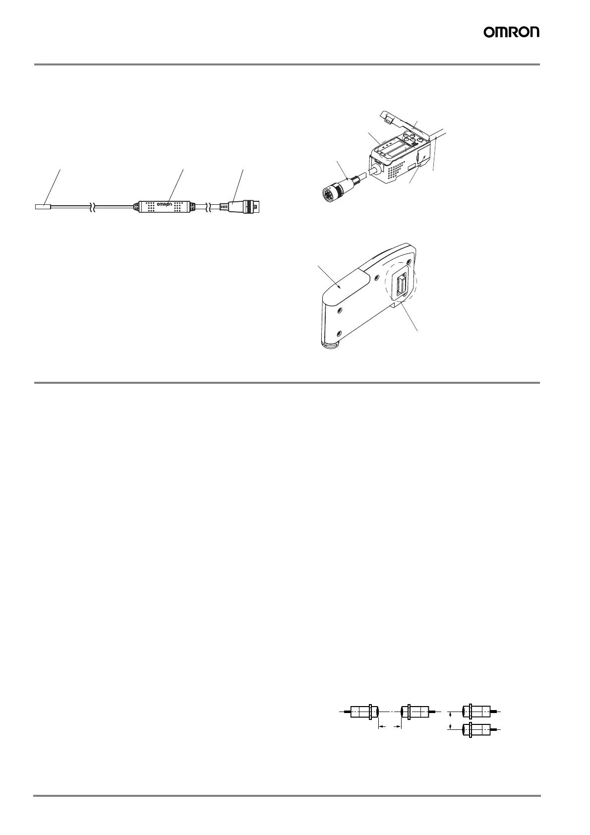
Part Names
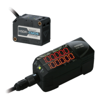
Sensors
ZX-EDR5T
ZX-ED01T
ZX-ED02T
ZX-EM02T
ZX-EM07MT
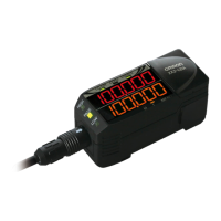
Amplifier Units
ZX-EDA11
ZX-EDA41
Calculating Unit
ZX-CAL / ZX-CAL2
Precautions
Design Precautions
Conform to the specified ratings and performance. Refer to
page B-65 Specifications for details.
Objects of certain materials or shapes may not be detectable,
or the detection accuracy may not be sufficiently high.
Environment
Do not operate the product in locations subject to flammable
or explosive gases.
In order to ensure safe operation and maintenance, do not in-
stall the product in the vicinity of high-voltage devices or pow-
er equipment.
Wiring
Do not use the product at voltages exceeding the rated val-
ues. Doing so may result in damage.
Do not connect the product to an AC power supply or connect
the power supply in reverse.
Do not short-circuit the load for open-collector output.
Do not lay the power cable for the product together with or in
the same duct as high-voltage lines or power lines. Doing so
may result in incorrect operation or damage due to induction.
Do not connect or disconnect connectors while the power is
ON. Doing so may result in damage.
Adjustment
Setting
When setting threshold values, ensure that the Amplifier
Unit’s judgement output hold input line is ON so that there is
no judgement output to external devices.
Other Precautions
Do not attempt to disassemble, repair, or modify the product.
Dispose of the product using standard procedures for indus-
trial waste.
These Sensors are not compatible with the ZX-L@@ Smart
Sensors (laser type). Do not connect combinations of
ZX-E@@ Smart Sensors and ZX-L@@ Smart Sensors.
Correct Use
Design Precautions
Power Supplies
Allow a warm-up period of approximately 30 minutes after
turning ON the power supply.
Mutual Interference
Up to 5 Sensor Heads can be used together by connecting the
ZX-CAL/ZX-CAL2 Calculating Unit between Amplifier Units.
When installing Sensor Heads facing each other or in parallel,
separate them by the minimum distances given in the table
below.
Sensor head
Preamplifier
Output cable
(with connector)
Input cable
(with connector)
Display area
Controls
Connector
(Cover opens and closes)
Output cable
Display area
Connector
A
B