Specifications and Dimensions
116
ZX2 User’s Manual
INTRODUCTION
MAIN
APPLICATIONS
& SETTING
METHODS
SPECIFI-
CATIONS
INDEX
SETTING
TRANSITION
CHARTS
DETAILED
SETTINGS
FLOW OF
OPERATION
CONTENTS
PREPARATION
FOR
MEASUREMENT
BASIC
SETUP
TROUBLE-
SHOOTING
Height
Double
Sheet
Detection
Positioning
Eccentricity
and Surface
Deflection
Steps
and
Warpage
Thickness
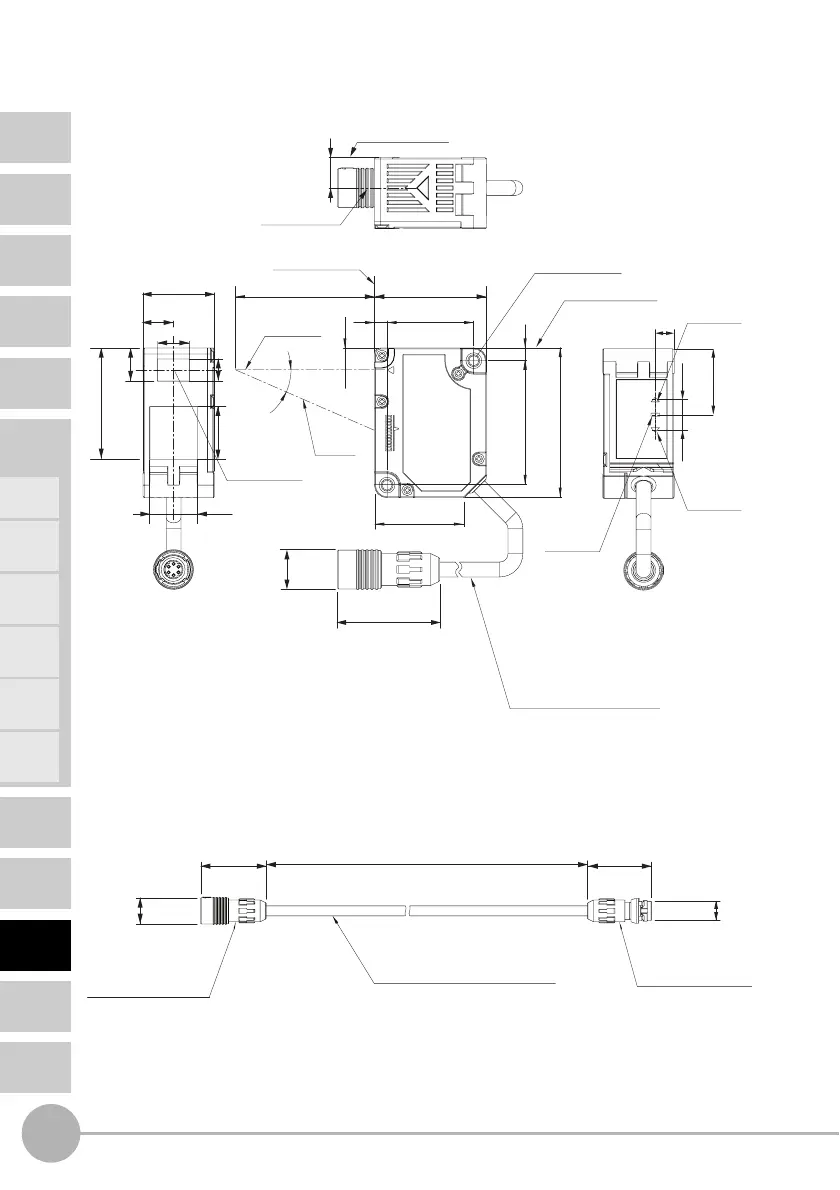
Sensor Heads
ZX2-LD50/LD50L
ZX2-LD100/LD100L
Sensor Head Extension Cables
Reference surface
Reference surface
Range
indicator
Range
indicator
Laser
warning
indicator
Reference surface
A
L
*
*
7
35.5
47.5
39.5
4
4
Two, 3.2-dia.
(mounting holes)
27.5
28.43
Emitter
axis
Receiver
axis
(9.7)
Emitter axis
22.6
29.8
12.6 dia.
9.7
35.3
16.7
10.5
Emitter center
6
20.9
4.84.8
* For ZX2-LD50 (L): L=50, A=21°
For ZX2-LD100 (L): L=100, 11.5°
Vinyl insulated round cable,
4.7 dia., 4 conductors
(Conductor cross-section
0.086 mm
2
/
Insulator diameter: 0.9 mm)
Standard length: 0.5 m
10.1
15.1
7
(Unit: mm)
29.8
28.9
L
12.3 dia.
8.9 dia.
*L Cable lengths are as follows:
ZX2-XC1R: 1 m, ZX2-XC4R: 4 m, ZX2-XC9R: 9 m
Note. Two or more extension cables cannot be connected in series.
Amplifier Unit
attachment connector
(female 6-pole)
Vinyl insulated round cable, 4.7 dia.
Sensor Head
attachment connector
(male, 6-pole)
(Unit: mm)
ZX2-XC1R
ZX2-XC4R
ZX2-XC9R

 Loading...


