Wiring Diagram
29
ZX2 User’s Manual
INTRODUCTION
BASIC
SETUP
PREPARATION
FOR
MEASUREMENT
TROUBLE-
SHOOTING
INDEX
CONTENTS
SETTING
TRANSITION
CHARTS
FLOW OF
OPERATION
MAIN
APPLICATIONS
& SETTING
METHODS
DETAILED
SETTINGS
SPECIFI-
CATIONS
Height
Double
Sheet
Detection
Positioning
Eccentricity
and Surface
Deflection
Steps
and
Warpage
Thickness
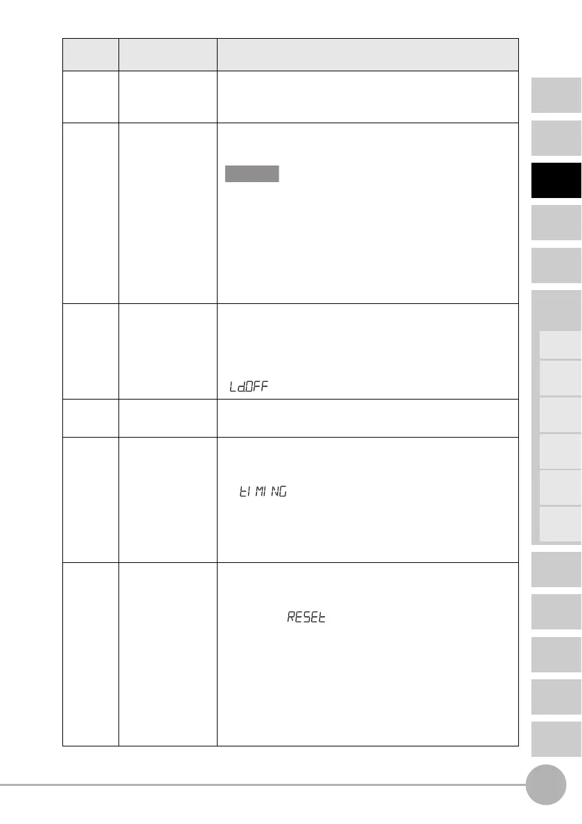
Cable
color
Name Function
Black Analog output The analog output outputs a current or voltage in
accordance with the measured value.
(For details on setting method, see page 95.)
Shield Analog GND (0 V) The analog GND terminal is the 0 V terminal for the analog
output.
• Use the shield for analog output separately from the blue
(0V) wire for power supply.
• When analog output is not used, be sure to connect this
wire to the blue (0 V) wire.
• When using Calculating Units, make sure that the analog
GND lines of the Amplifier Units are connected to each
other.
Pink LD-OFF input If this LD-OFF input signal is ON, the laser will stop
emission, causing a light intensity error. In this case, the
analog output, digital display, judgement output, and
judgement output display signals will be output according to
the non-measurement settings. The sub-display will show
.
Orange Zero reset input The zero reset input is used to execute and cancel zero reset.
(For details, see page 87.)
Purple Timing input/
BANK input 0
(switched by
external input
setting)
Timing input:
Signal input wire for obtaining hold function timing. While
this input is being input, the sub-display will show
.
BANK input 0:
Signal input wire for bank switching. Banks are switched
by ON/OFF combinations with BANK input 1.
(For details on switching and inputs, see page 101.)
Red Reset input/BANK
input 1 (switched
by external input
setting)
Reset input:
The reset input resets all measurement processing and
outputs. While reset input is being input, the sub-display
will show . The analog and judgement output
signals will be output according to the non-measurement
settings. If this reset input switches ON while the hold
function is used, the state in effect before the hold
function was set will be restored.
BANK input 1:
Signal input wire for bank switching. Banks are switched
by ON/OFF combinations with BANK input 0.
(For details on switching and inputs, see page 101.)
Important

 Loading...


