2. Position the piston on the connecting rod. In-
stall the piston pin. The piston pin is a full-float-
ing type, and must be kept in place (in the pis-
ton) with two lock rings,
one
at each side. In-
stall the lock rings and ensure they are prop-
erly in place before installing
the
piston and
connecting rod in the engine.
3. Install the rings
on
the piston beginning with
the oi! control ring (Figure 9-27). Use a piston
ring spreader to prevent twisting
or
excessive
expansion
of
the ring. Compression rings are
marked with a
dot
or
the word "top" on one side
of
the ring to indicate which side faces the top
of
the piston. Unmarked piston rings can be in-
stalled either way. The oil control ring has an
expander. Install the
expander
first, then close
until the
expander
ends
butt together. Locate
the expander
gap
180 degrees from the ring
gap. Make certain that the piston ring gaps are
not
aligned with
one
another.
EXPANDER
CT1047s
RGURE
9-27. PISTON RINGS
Piston Installation Procedure
1. Turn
the
crankshaft
to
position
the
#1
rod bear-
ing journal
at
the bottom
of
its stroke.
2. Lubricate
the
#1
piston assembly and the in-
side
ofthe
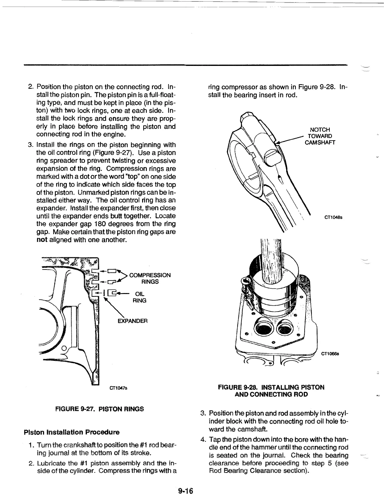
cylinder. Compress the rings with a
9-16
ring compressor as shown in Figure 9-28. In-
stall the bearing insert in rod.
NOTCH
TOWARD
CAMSHAFT
CT1048s
CT1066s
FIGURE 9-28. INSTALLING PISTON
AND CONNECTING ROD
3. Position
the
piston and rod assembly in the cyl-
inder block with the connecting rod
oil hole to-
ward
the
camshaft.
4. Tap
the
piston down into the bore with the han-
dle
end
of
the
hammer
until
the
connecting rod
is seated on the journal. Check
the
bearing
clearance before proceeding
to
step 5 (see
Rod Bearing Clearance section}.
 Loading...