(>
0
0
0
0
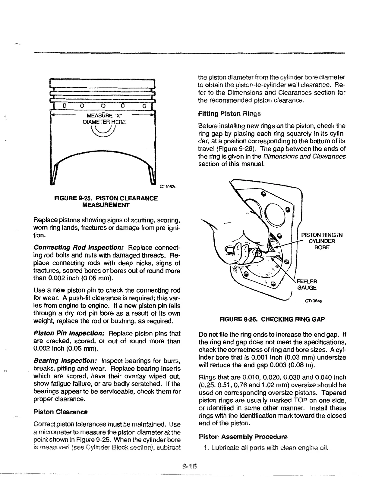
MEASURE "X"
DIAMETER HERE
'01
0
FIGURE 9-25. PISTON CLEARANCE
MEASUREMENT
CT1063s
Replace pistons showing signs
of
scuffing, scoring,
worn ring lands, fractures
or
damage from pre-igni-
tion.
Connecting Rod Inspection: Replace connect-
ing rod bolts and nuts with damaged threads. Re-
place connecting rods with deep nicks, signs
of
fractures, scored bores
or
bores out of round more
than
0.002 inch (0.05 mm).
Use a new piston pin
to
check the connecting rod
for wear.
A push-fit clearance is required; this var-
ies from engine to engine. If a new piston pin falls
through a
dry
rod pin bore
as
a result of its own
weight, replace the rod
or
bushing,
as
required.
Piston Pin Inspection: Replace piston pins that
are cracked, scored,
or
out
of
round more than
0.002 inch (0.05 mm).
Bearing Inspection: Inspect bearings for burrs,
breaks, pitting and wear. Replace bearing inserts
which are scored, have their overlay wiped out,
show fatigue failure, or are badly scratched.
If
the
bearings appear to be serviceable, check them for
proper clearance.
Piston Clearance
Correct piston tolerances must be maintained. Use
a micrometer to measure the piston diameter at the
point shown
in Figure 9-25. When the cylinder bore
is (see Cylinder Block section),
-
'"
'<::.&
the piston diameter from the cylinder bore diameter
to obtain the piston-to-cylinder wall clearance. Re-
fer
to the Dimensions and Clearances section for
the recommended piston clearance.
Fitting Piston Rings
Before installing new rings on the piston, check the
ring gap by placing each ring squarely in its cylin-
der, at a position corresponding to the bottom
of
its
travel (Figure
9-26). The gap between the ends
of
the ring is given in the Dimensions
and
Clearances
section
of
this manual.
PISTON RING IN
CYUNDER
BORE
CT1064s
FIGURE 9-26. CHECKING RING
GAP
Do not file the ring ends to increase the end gap. If
the ring end gap does not meet the specifications,
check the correctness
of
ring and bore sizes.
Acyl-
inder bore that is 0.001 inch (0.03 mm) undersize
will reduce the end gap
0.003 (0.08 m).
Rings that are
0.01 0, 0.020, 0.030 and 0.040 inch
(0.25, 0.51, 0.76 and 1.02 mm} oversize should be
used on corresponding oversize pistons. Tapered
piston rings are usually marked TOP on one side,
or
identified in some other manner. Install these
rings with
the identification mark toward the closed
end of the piston.
Piston
Assembly Procedure
1. Lubricate all parts with clean engine oil.
 Loading...