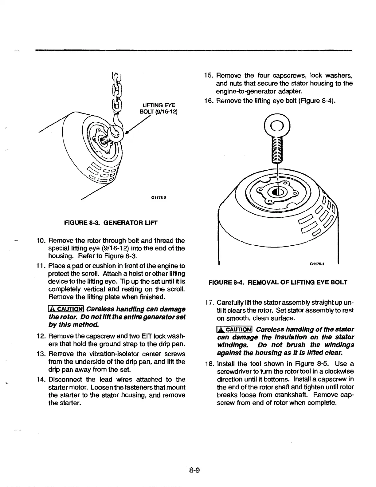
UFTING
EYE
~T(9/16-12j
G1176-2
FIGURE 8-3. GENERATOR
UFT
1 0. Remove the rotor through-bolt and thread the
special lifting eye (9/16-12) into the end
of
the
housing. Refer to Figure 8-3.
11. Place a pad
or
cushion in front
of
the engine to
protect the scroll. Attach a hoist
or
other lifting
device to the lifting eye. Tip up the set until
it is
completely vertical and resting on the scroll.
Remove the lifting plate when finished.
lA
CAUTION!
Careless
handling
can damage
the rotor. Do
not
lift
the entire generator
set
by
this method.
12. Remove the capscrew and two EIT lock wash-
ers that hold the ground strap to the drip pan.
13. Remove the vibration-isolator center screws
from the underside of the drip pan, and lift the
drip pan away from the set.
14. Disconnect the lead wires attached to the
starter motor. Loosen the fasteners that mount
the starter to the stator housing, and remove
the starter.
15. Remove the four capscrews, lock washers,
and nuts that secure the stator housing to the
engine-to-generator adapter.
16. Remove the lifting eye bolt (Figure 8-4).
G1175-1
FIGURE 8-4. REMOVAL
OF
UFTING EYE BOLT
17. Carefully lift the stator assembly straight up un-
ti
I it clears the rotor. Set stator assembly to rest
on smooth, clean surface.
lA
CAUTION!
Careless handling
of
the
stator
can damage the Insulation
on
the
stator
windings. ·
Do
not
brush
the
windings
against
the
housing
as
It
Is
lifted
clear.
18. Install the tool shown in Figure 8-5. Use a
screwdriver to turn the rotor tool in a clockwise
direction until
it bottoms. Install a capscrew in
the end
of
the rotor shaft and tighten until rotor
breaks loose from crankshaft. Remove cap-
screw from end of rotor when complete.
 Loading...