ROTOR
TOOL
/
10 IN. (254 mm)
(7/16-14)
G1175
FiGURE 8-5. ROTOR TOOL
19. Carefully lift the rotor assembly
off
the end
of
the engine crankshaft and remove rotor tool.
20.
Uft
the brush wires and remove brush holding
wire from housing. Remove the brush block
mounting screw and carefully remove the
brush block assembly from the stator housing.
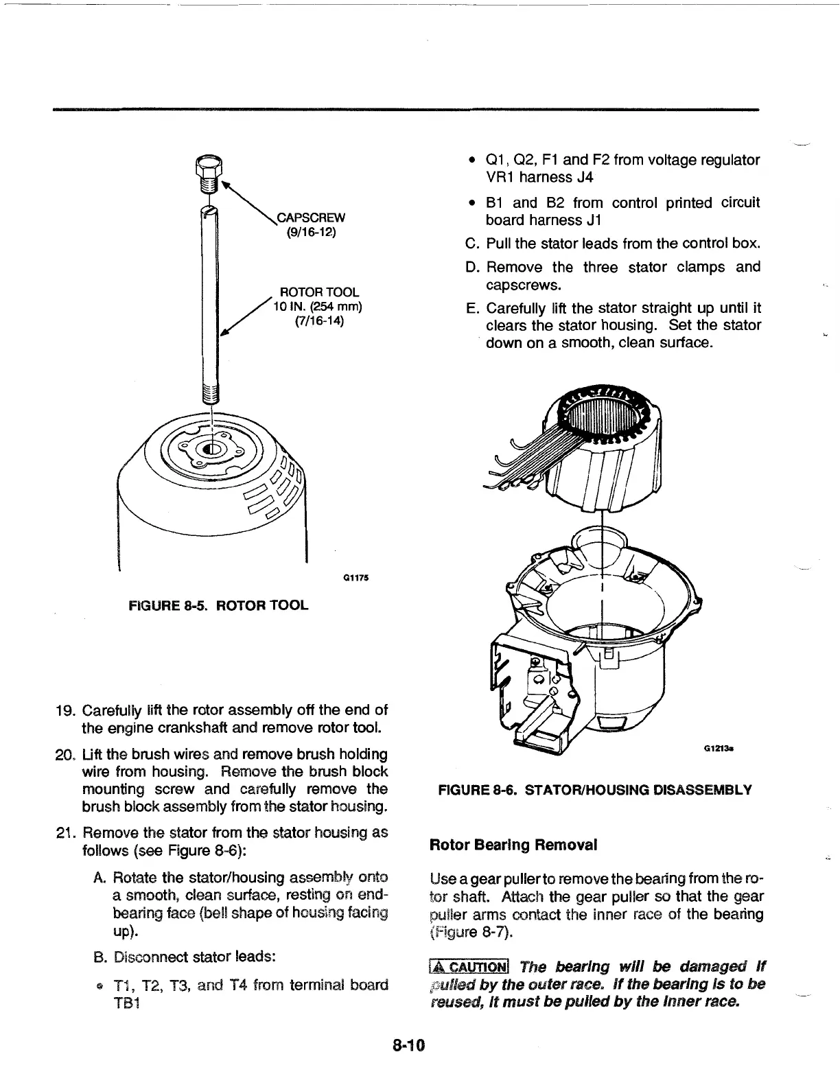
21. Remove the stator from the stator housing
as
follows {see Figure 8-6):
A.
Rotate the stator/housing assembly onto
a smooth, clean surface, resting on end-
bearing face (bel! shape
of
housing facing
up).
B.
Disconnect stator leads:
* T1, T2, T3, and T 4 from terminal board
TB1
8-10
• 01 ,
02,
F1
and F2 from voltage regulator
VR
1 harness J4
•
81
and
82
from control printed circuit
board harness
J1
C.
Pull the stator leads from the control box.
D.
Remove the three stator clamps and
cap screws.
E.
Carefully lift the stator straight up until it
clears the stator housing. Set the stator
down on a smooth, clean surface.
G1213s
FIGURE 8-6. STATOR/HOUSING DISASSEMBLY
Rotor Bearing Removal
Use a
gear
puller
to
remove the bearing from the ro-
tor
shaft. Attach the
gear
puller so that the
gear
puller arms contact the inner race of the bearing
(Figure 8-7).
lA
CAUTION!
The bearing
will
be
damaged
If
pulled
by
the
outer
race.
If
the bearing Is to
be
reused,
It
must
be
pulled
by
the
Inner
race.
 Loading...